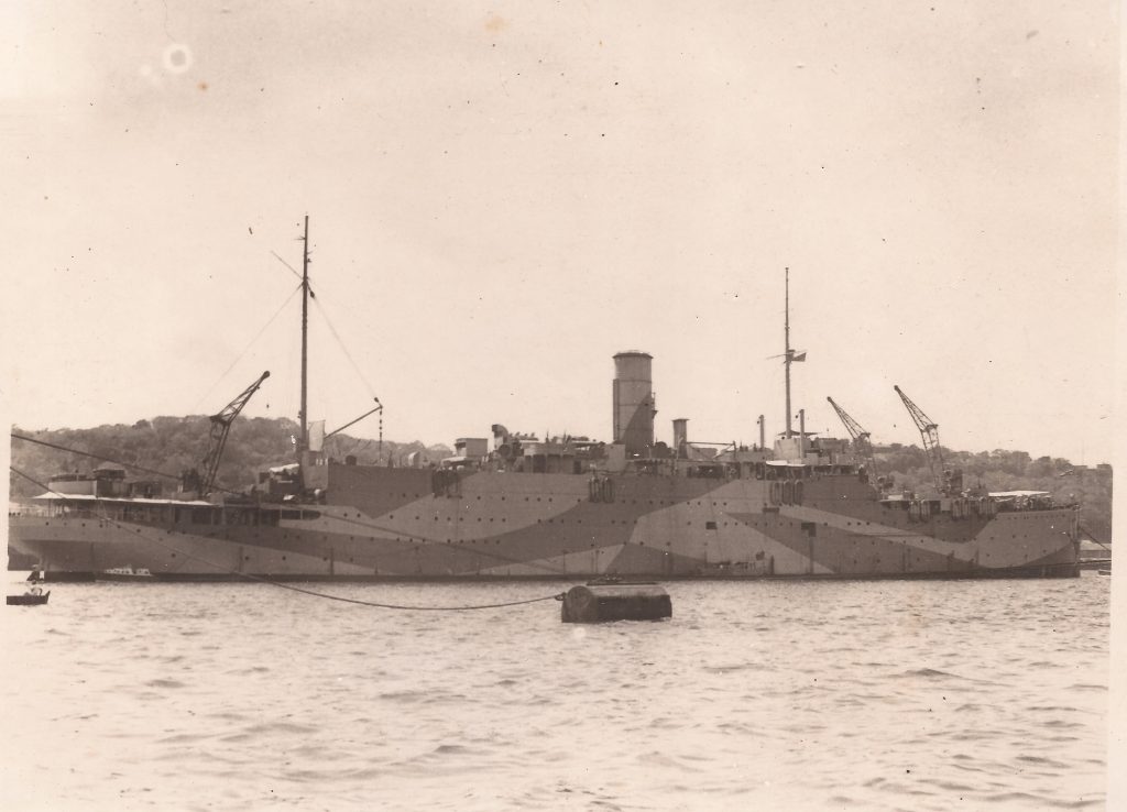
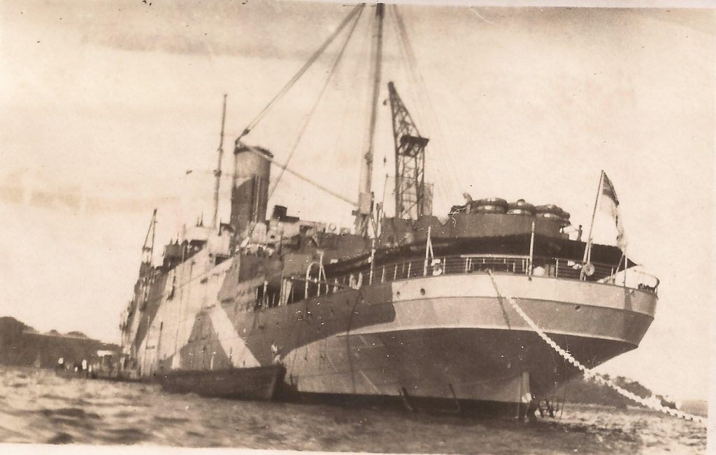
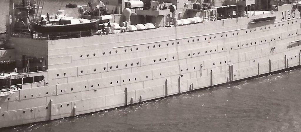
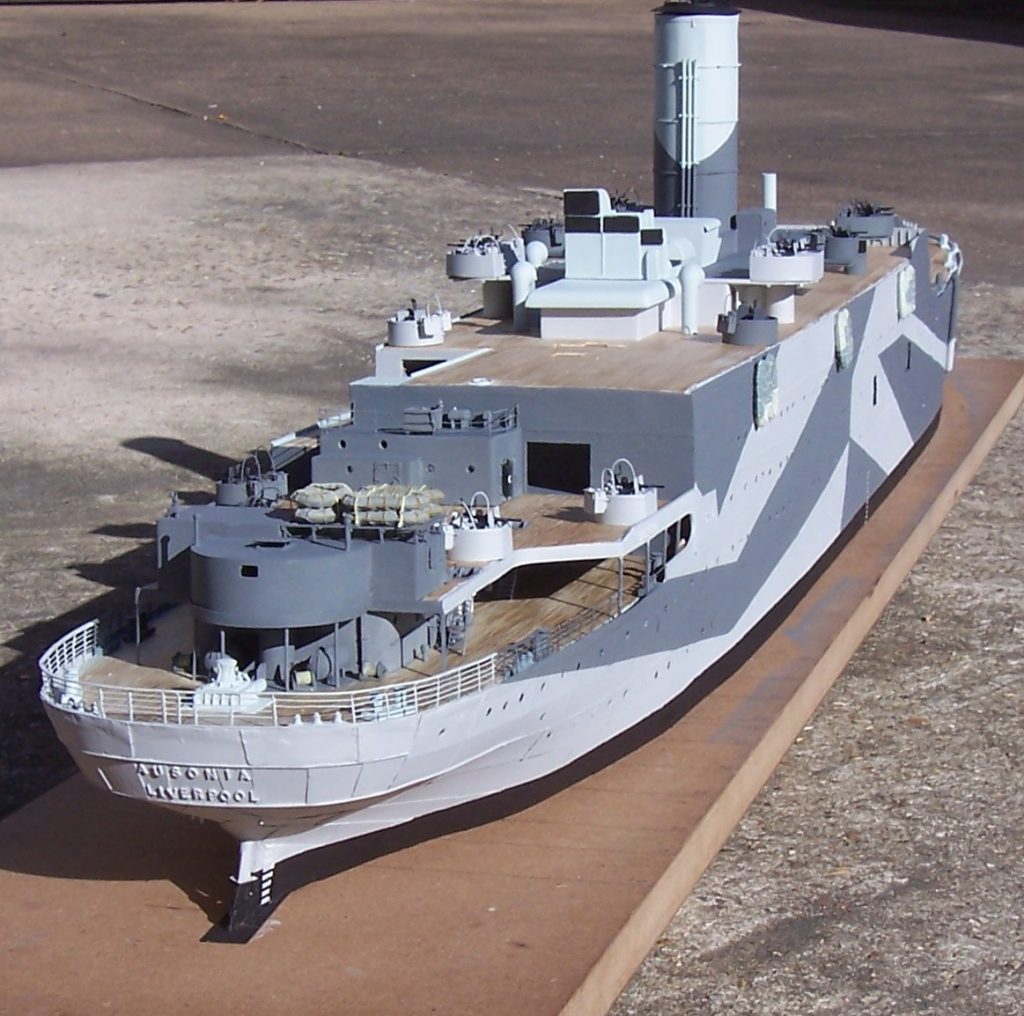
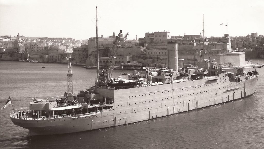
Inspiration for this model came from my father, Ron who served on the Ausonia between November 1945 and April 1946 at Trincomalee, Ceylon. To start with the only photograph of the ship that I had was the souvenir photograph taken in Trincomalee Bay, in 1945, which was given to him at the time.
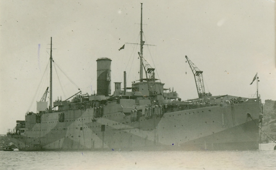
I was able to locate several more post war photographs of the ship, but these were after she had under gone several major refits and as I wanted to depict the ship as she would have been in late 1945, they were only of limited value. Recently I have acquired a collection of photographs from a former Ausonia crew member, which include two more photographs which would appear to have been taken at the same time in Trincomalee Bay.
After several years of research, I concluded that with photographic evidence in short supply I would have to rely on the General Arrangement ships plans for details of her structure and fittings. Contact with the National Maritime Museum revealed that they held the plans for the Ausonia’s hull and details of when she had been converted to an Armed Merchant Cruiser, but nothing for when she was a Heavy Repair Ship. The hull plans were ordered and I decided to base my model on the plans of her sister ship, HMS Artifex, which although not identical, were the best that I could hope for as I could not locate any plans for the Ausonia from any other source.
The idea that I could produce the only scratch built scale model of HMS Ausonia was greatly challenged when my copy of the hull blue prints arrived. The plans had been drawn by the Cunard draughtsmen to a scale of 1/48 or ¼” equals 1 foot. The drawing sheet was nearly 16 feet long and I came to realise what a daunting task I had set myself.
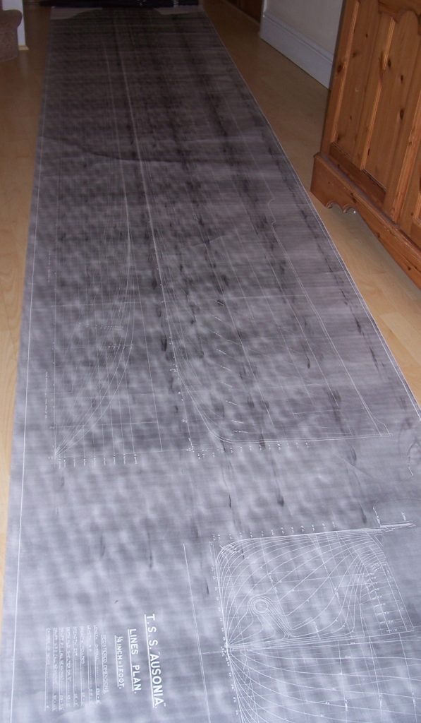
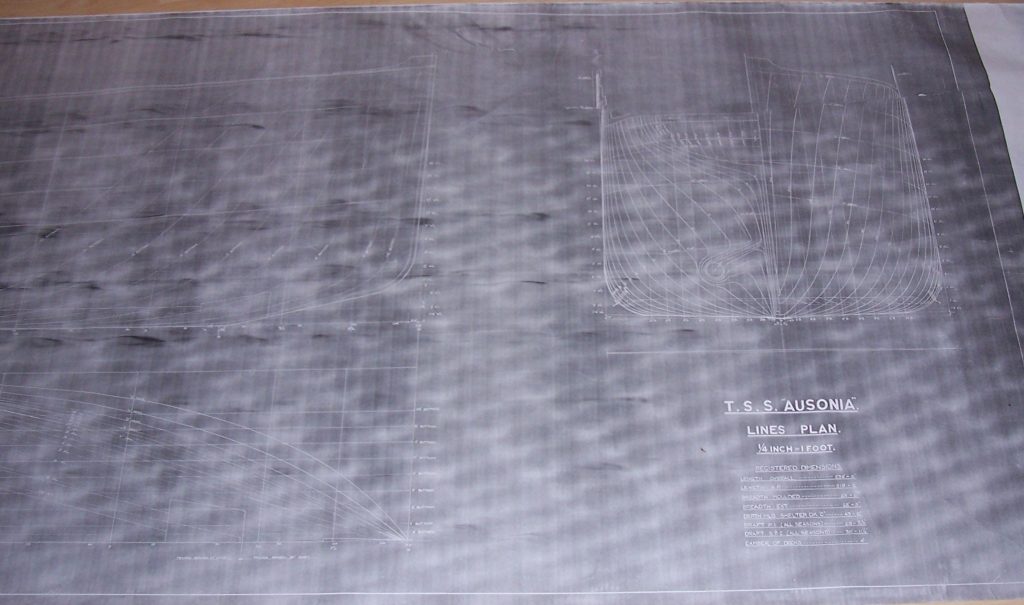
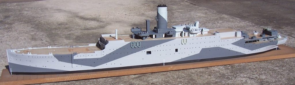
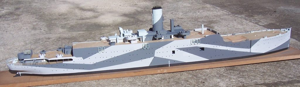
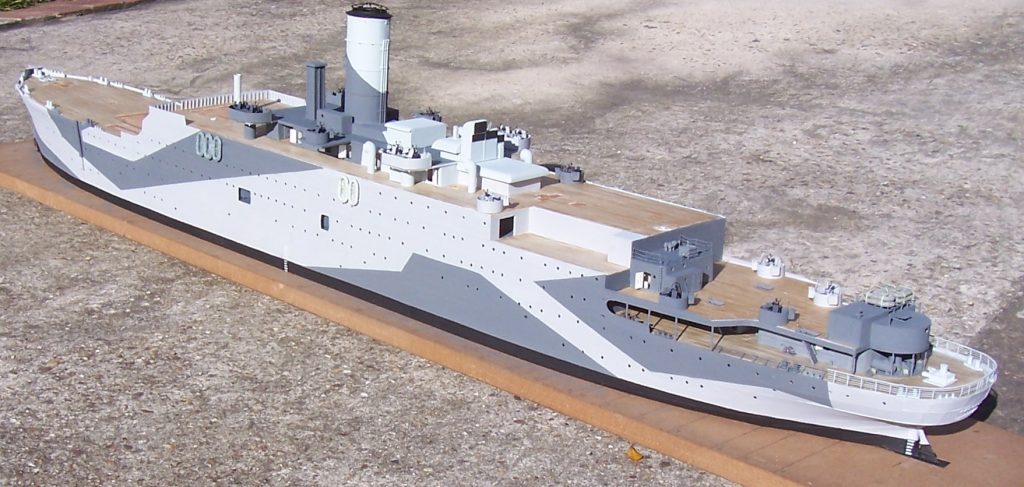
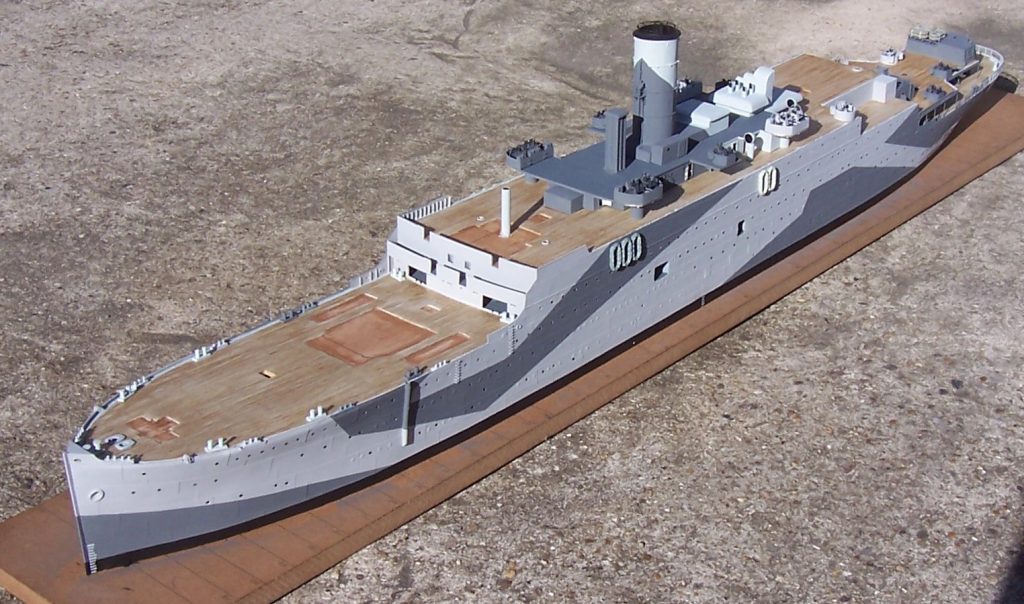
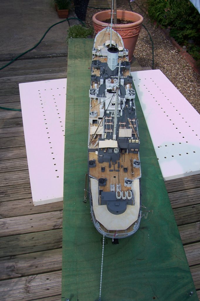
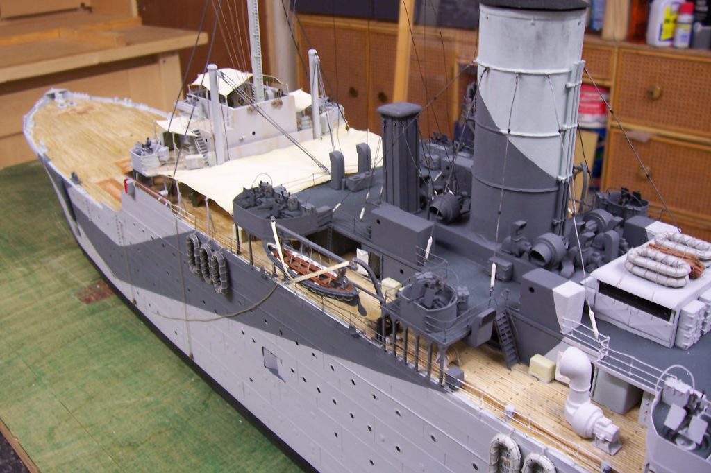
I had decided to build the model to a scale of 1/128 which means that every 12” on the full size ship, equates to 3/32” on the model. Not the normal scale for a model ship, which is generally 1/96 scale, but as the hull of Ausonia was 538 feet, when scaled down to 1/128 scale, would give me a manageable model length of 52”. My first task was therefore to reduce the size of the hull plans down to the same scale that my model would be built to, that way I would able to take measurements directly from the plans themselves.
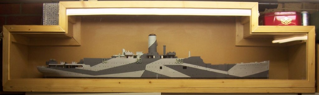
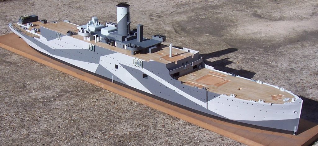
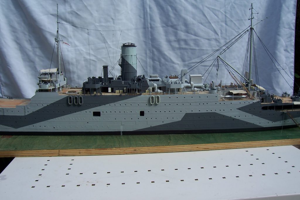
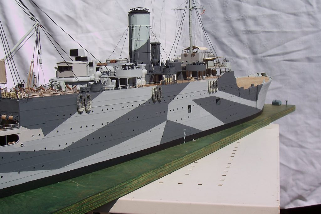
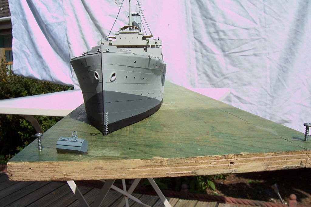
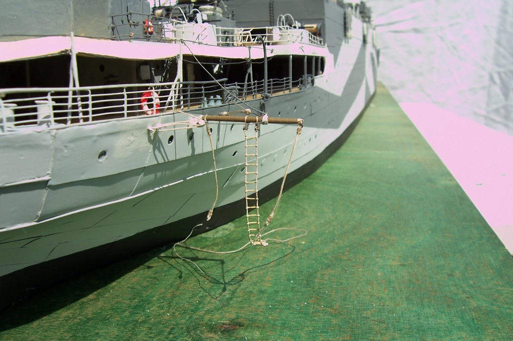
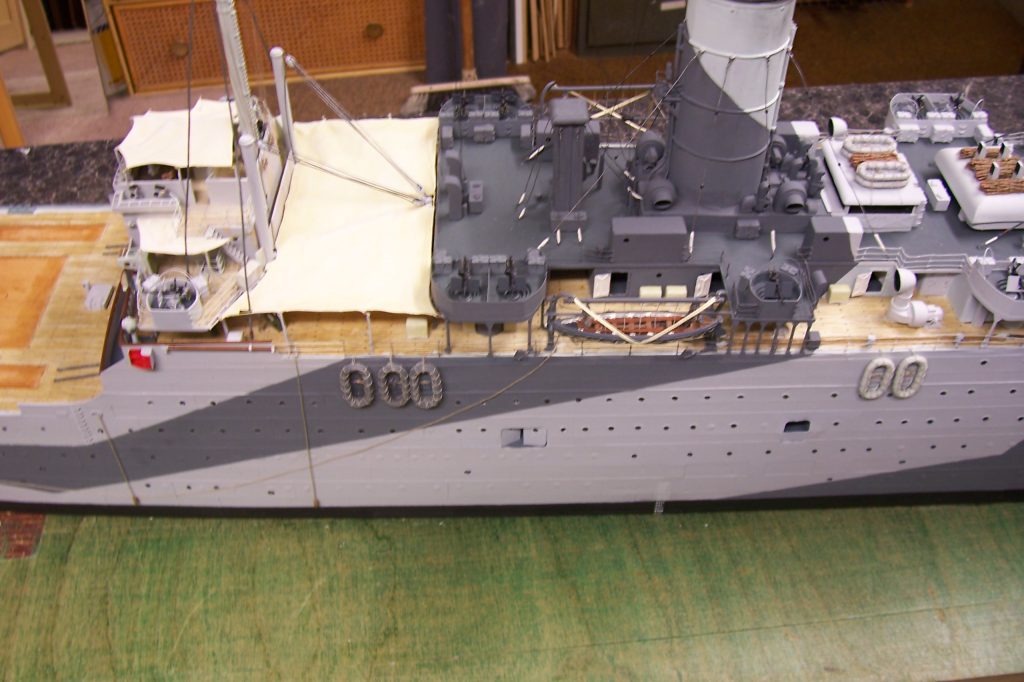
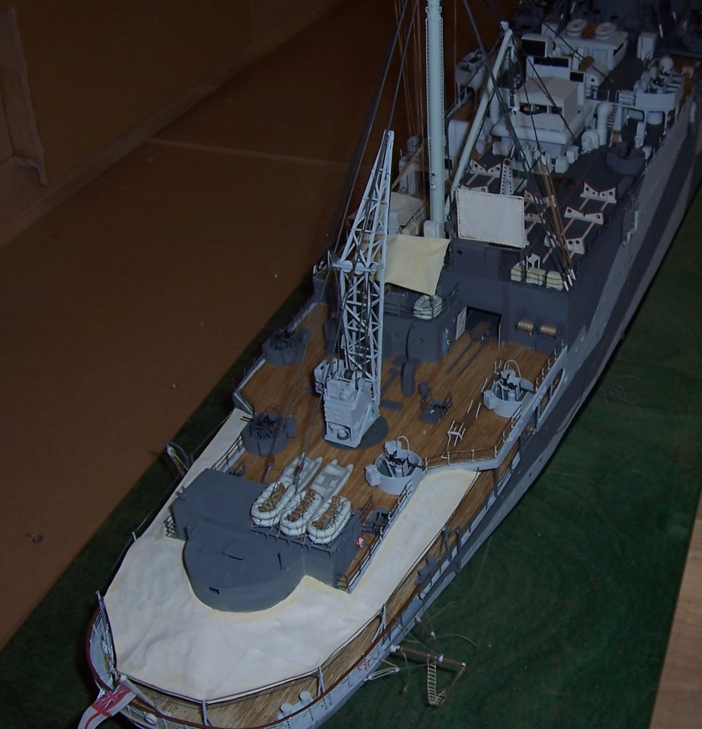
From the very beginning I had decided to build the ship as a waterline model, mainly because I wanted to depict the model just as she would have appeared in the photograph, taken at Trincomalee in 1945, but also having had a few mishaps whilst sailing some of my previous model boats, I did not want to take the risk of damaging it once complete.
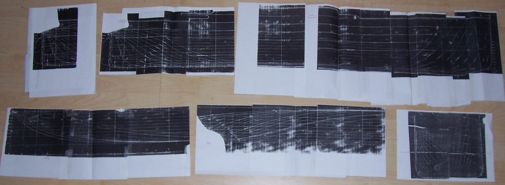
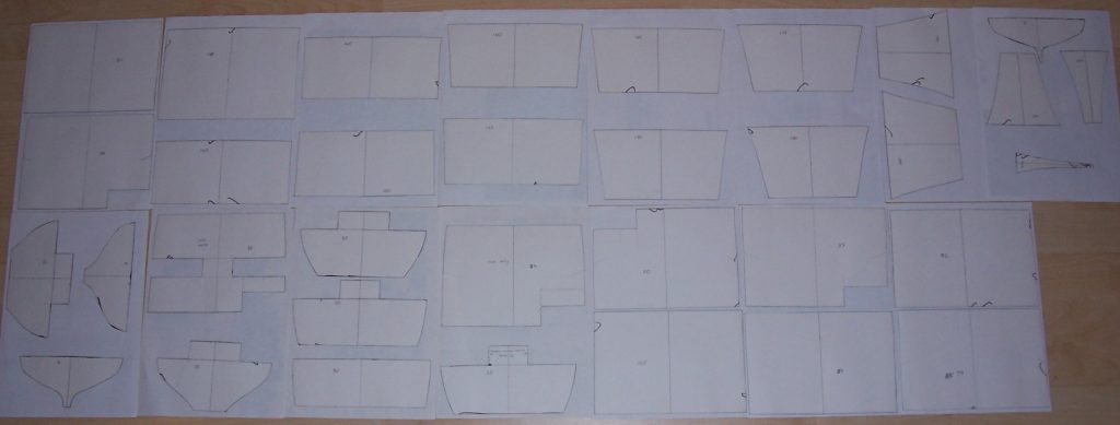
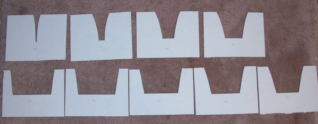
With the plans reduced, 35 profile sheets where printed off, one for each of the frame stations portrayed on the drawing. The profile sheets were then used to produce profile templates, which were made from thick card and would be used to shape the model hull down to the waterline.
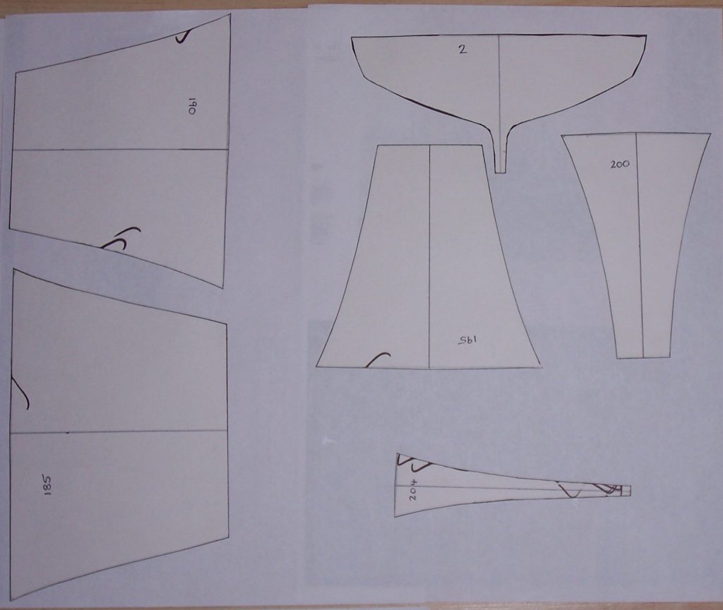
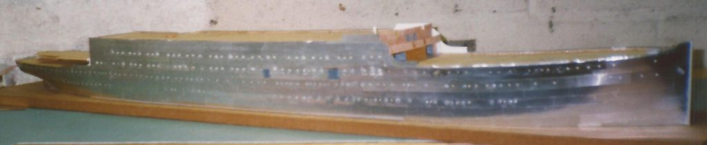
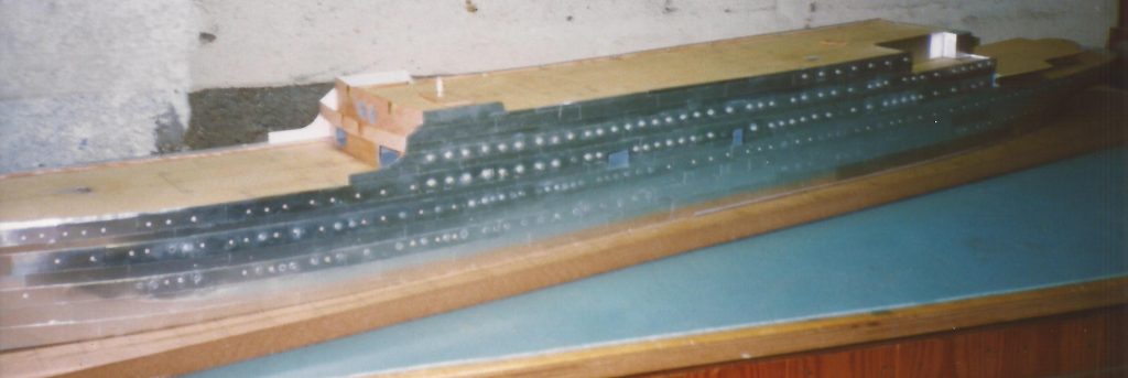
The hull of the model is made in what is known as the “Bread and Butter” construction method, using balsa and Jelutong, which are both low density woods making it very easy to work with. A sheet of plywood is used as the base, which is just below the waterline, with the frame stations accurately drawn. The balsa and Jelutong blocks were then stuck to this and shaped to the correct hull profile using the frame station templates.
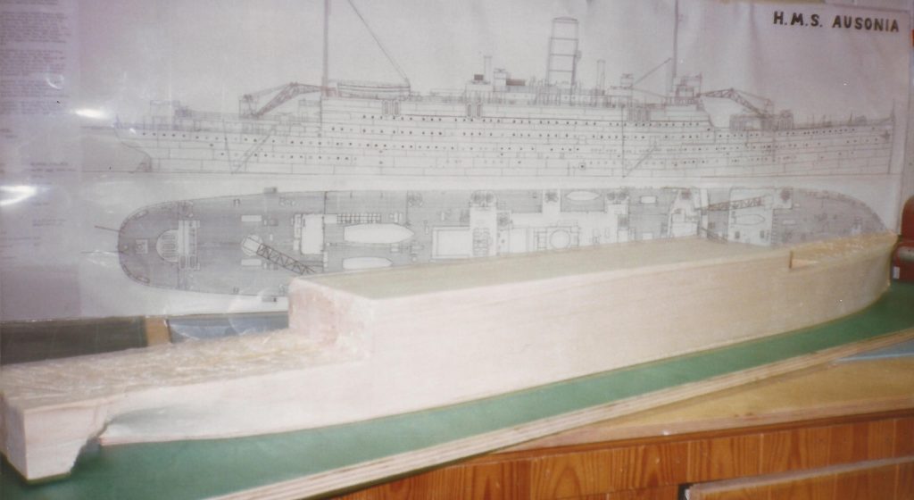
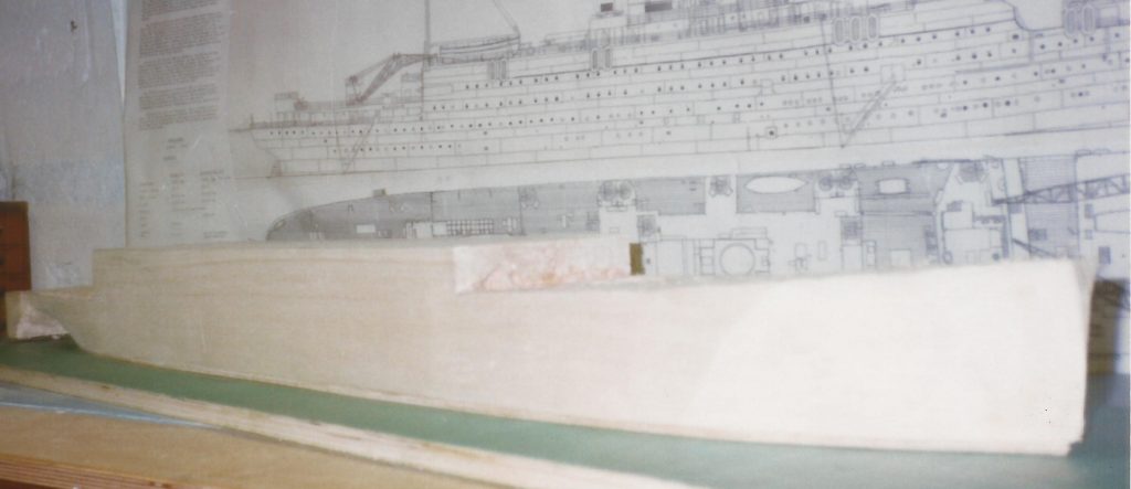
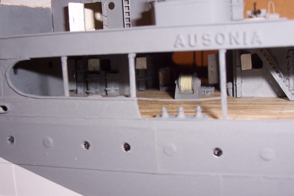
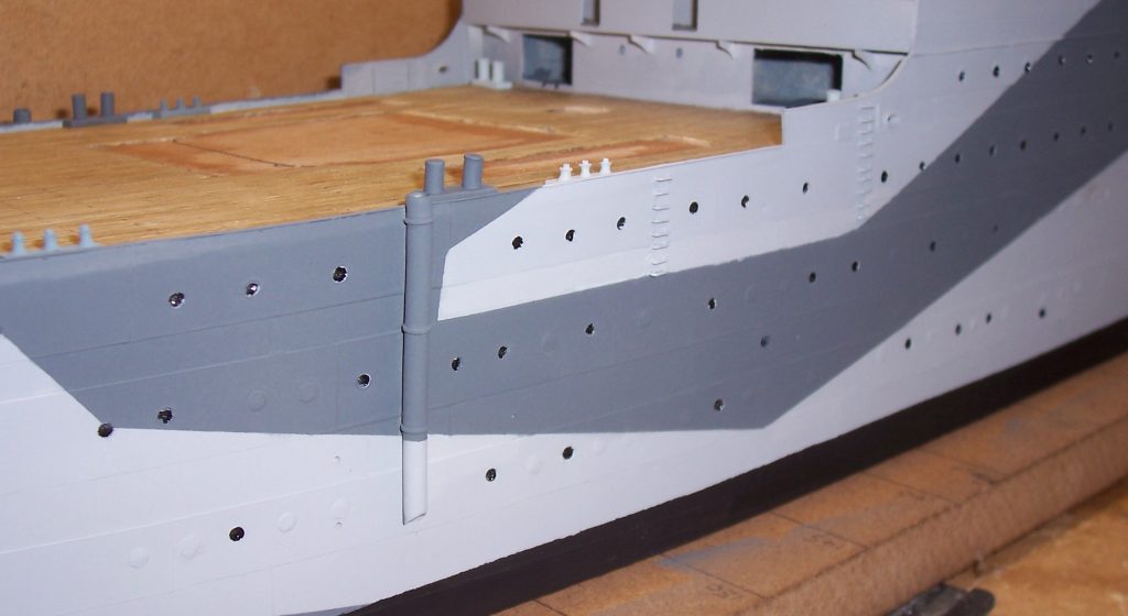
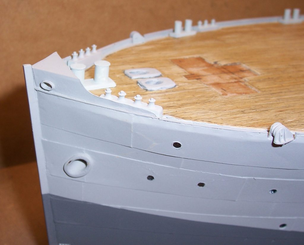
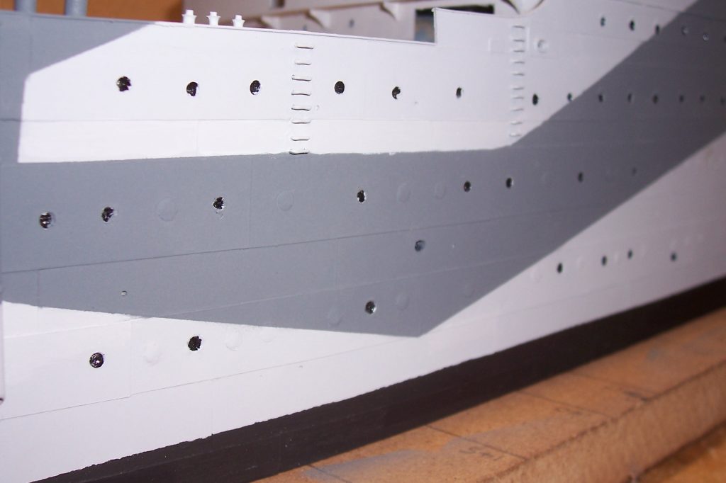
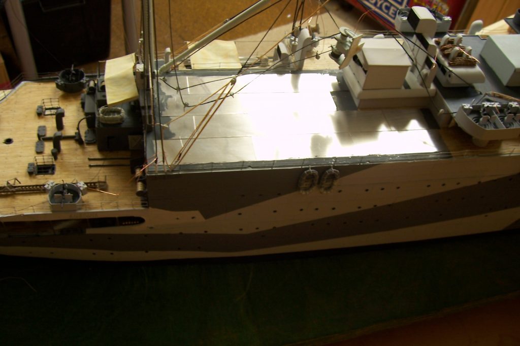
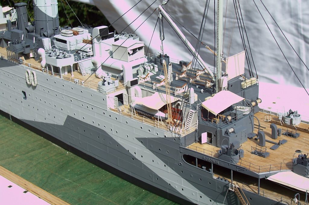
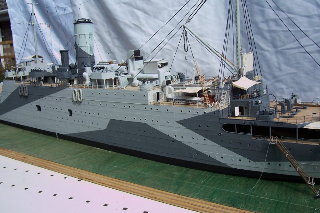
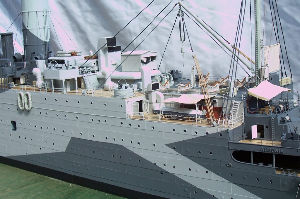
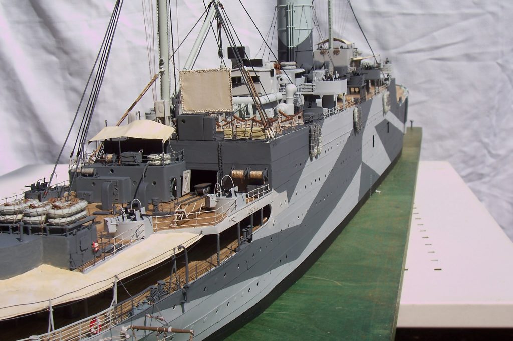
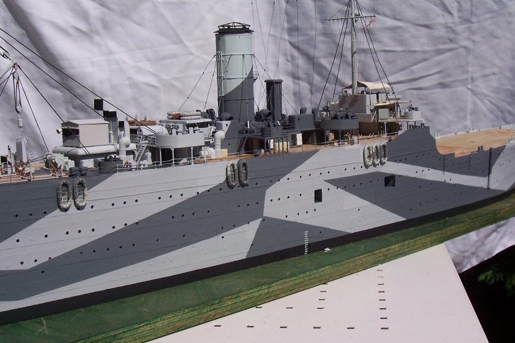
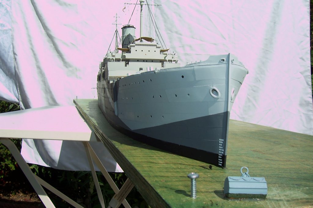
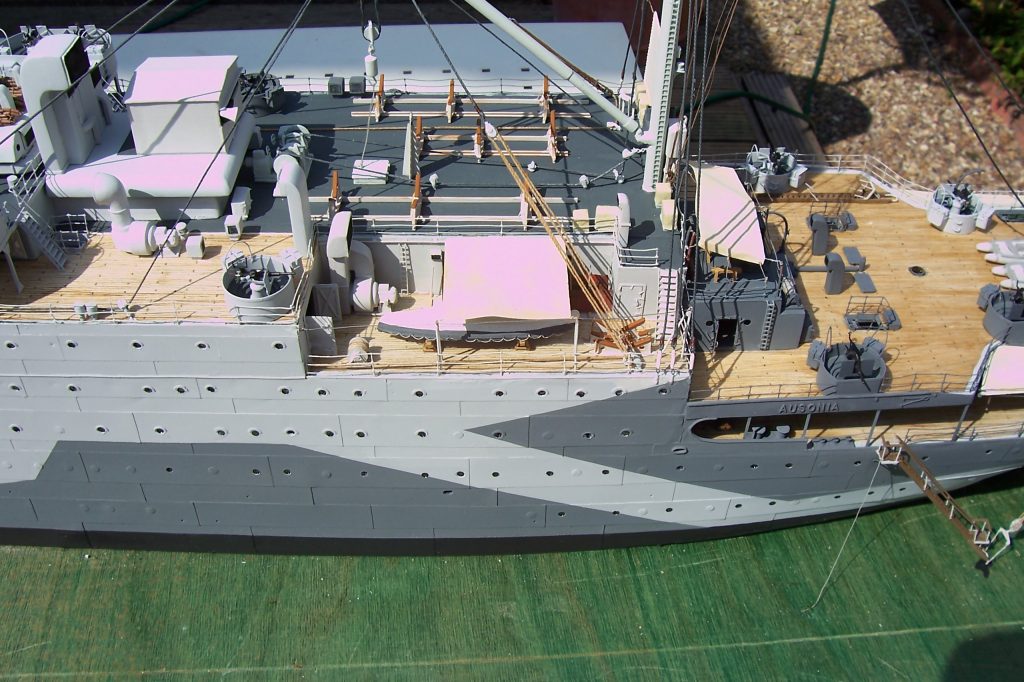
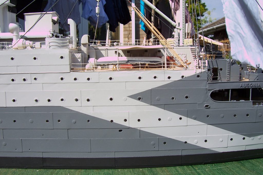
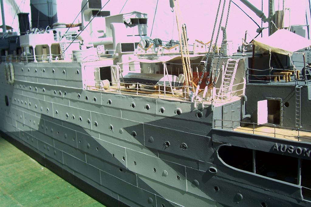
Once the hull had been shaped, plywood decks were added and the shell plating, which was represented, using 0.004” aluminium sheet, cut to the correct size and adhered to the hull.
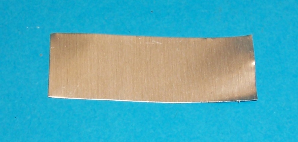
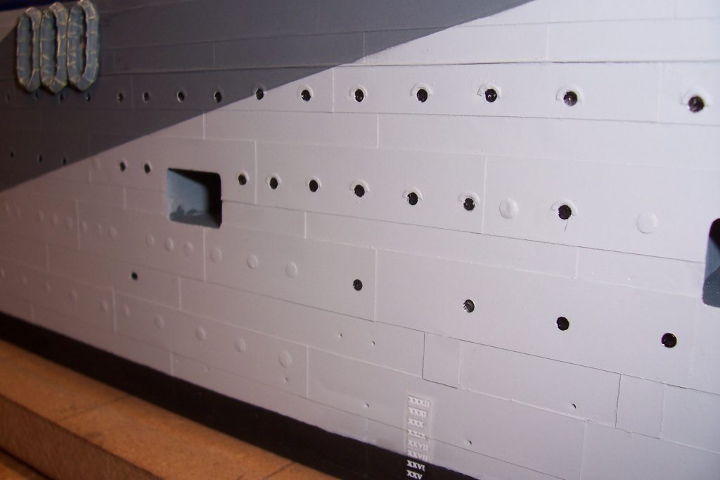
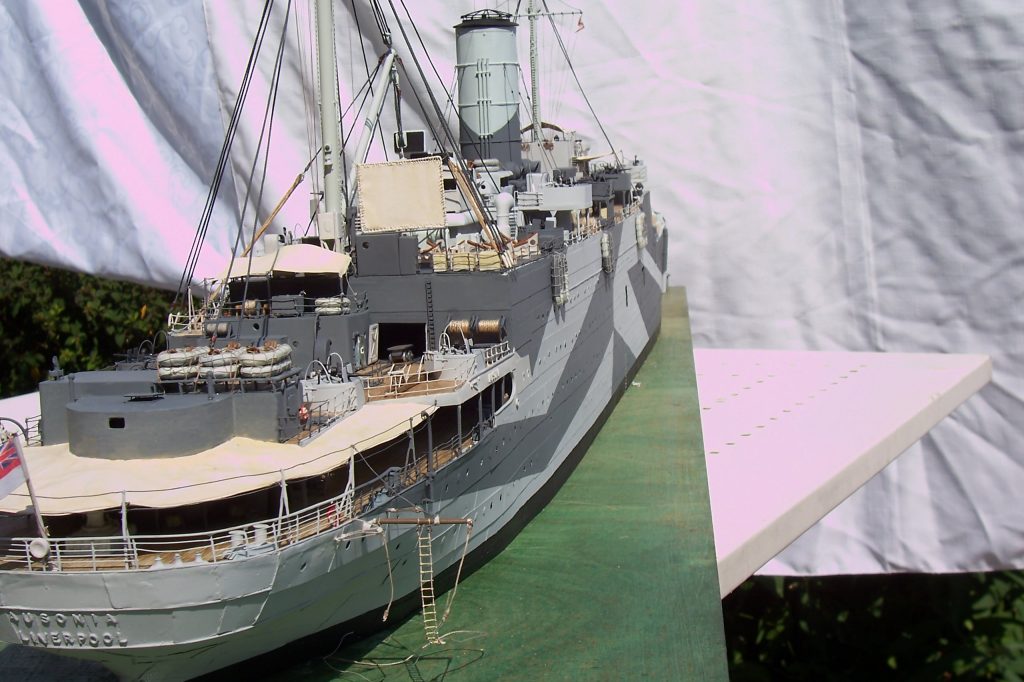
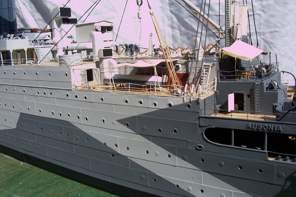
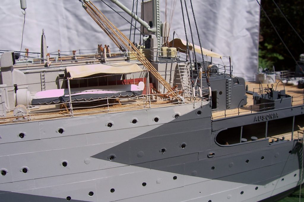
With the hull painted, the result is a fair representation of the ships shell plating and I hope that I have made it look realistic, having faithfully copied every plate as per the original.
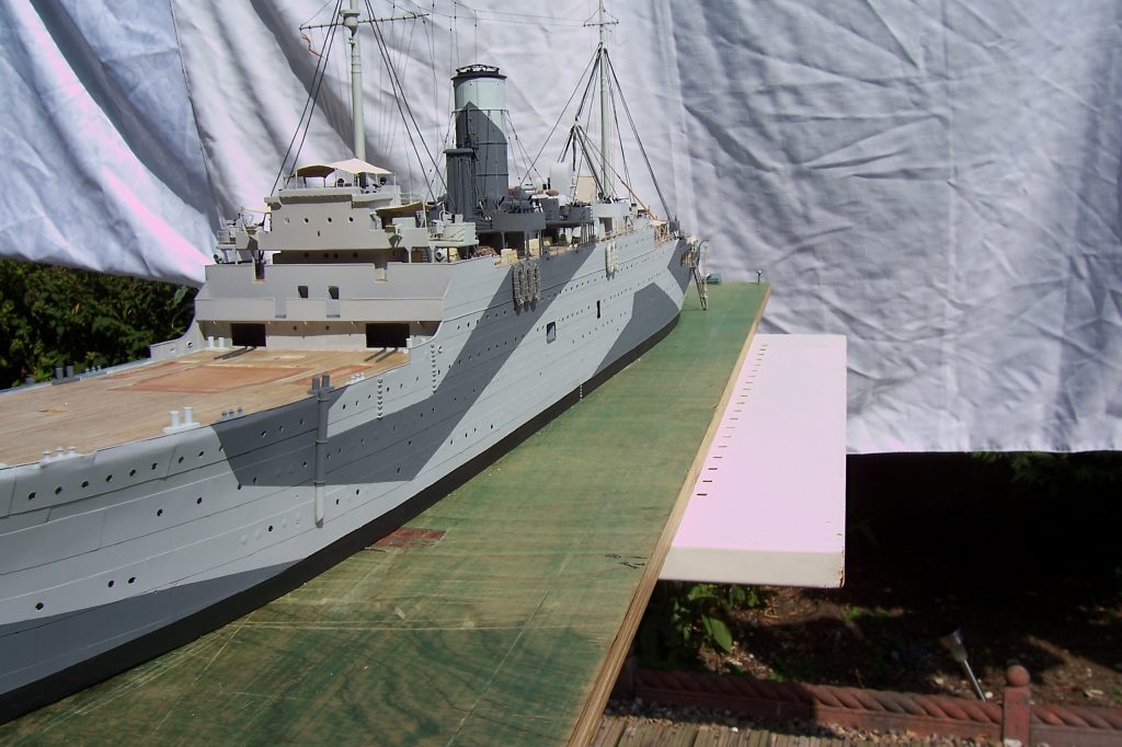
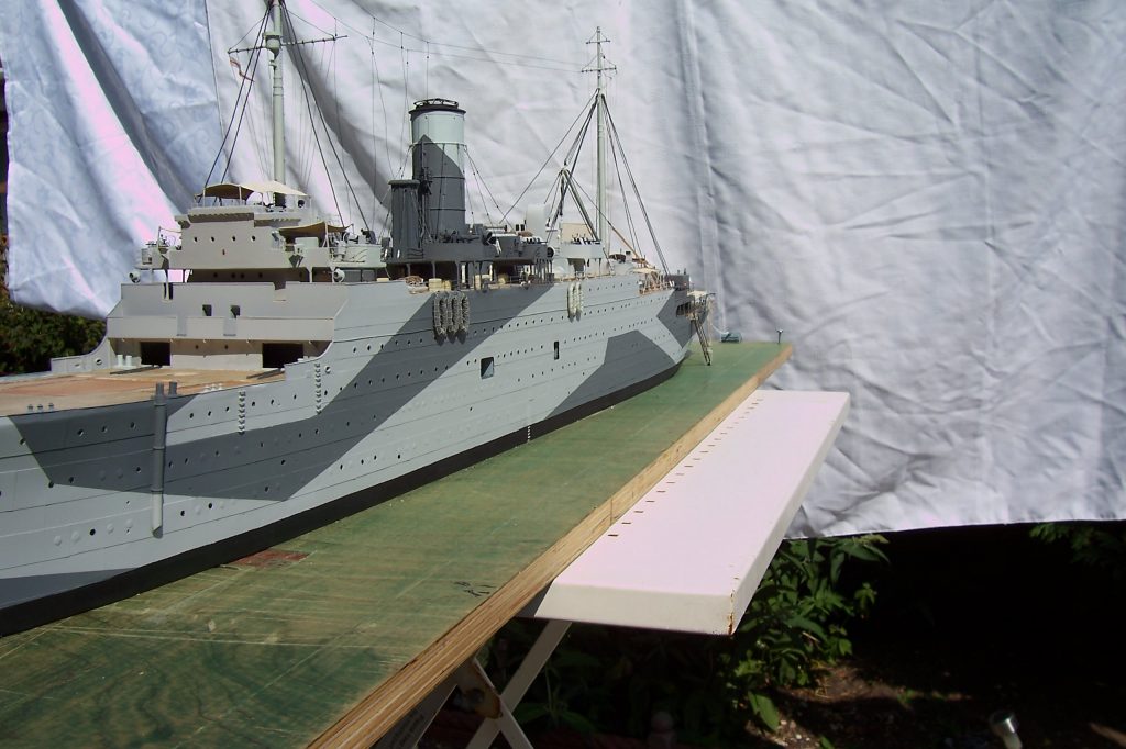
Although many years in the making, the model is still only partially complete as the majority of the model has been scratch built, a very time consuming task when you take in the time that is required to research every part, ensuring authenticity.
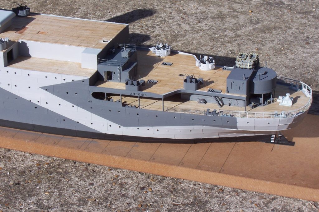
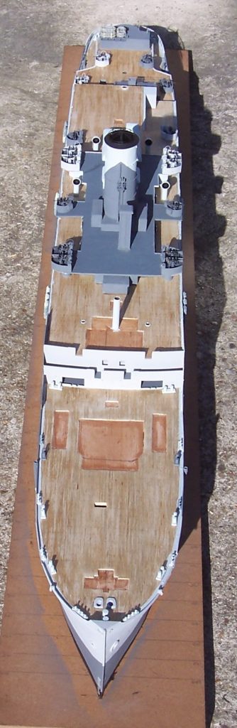
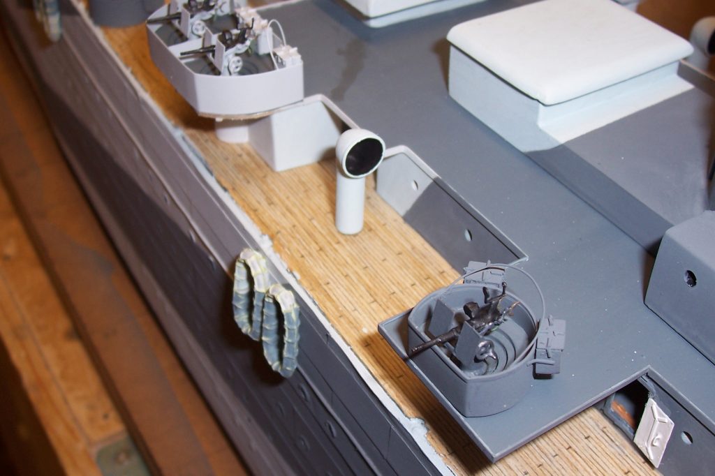
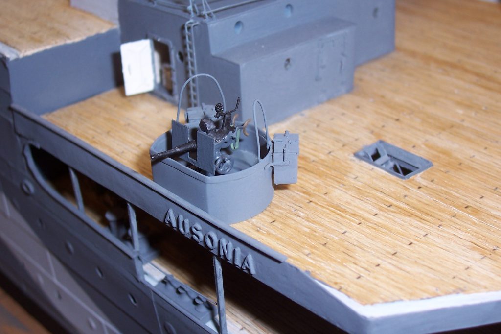
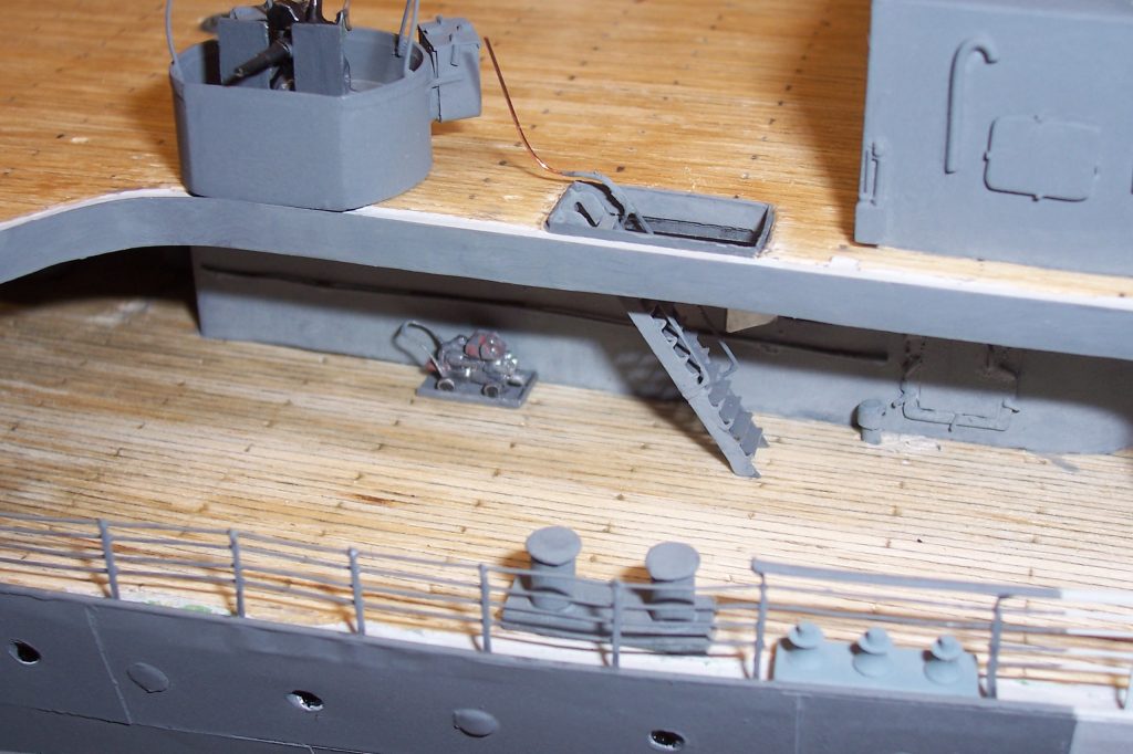
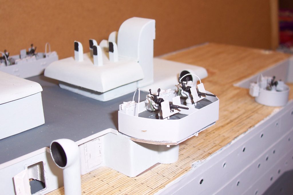
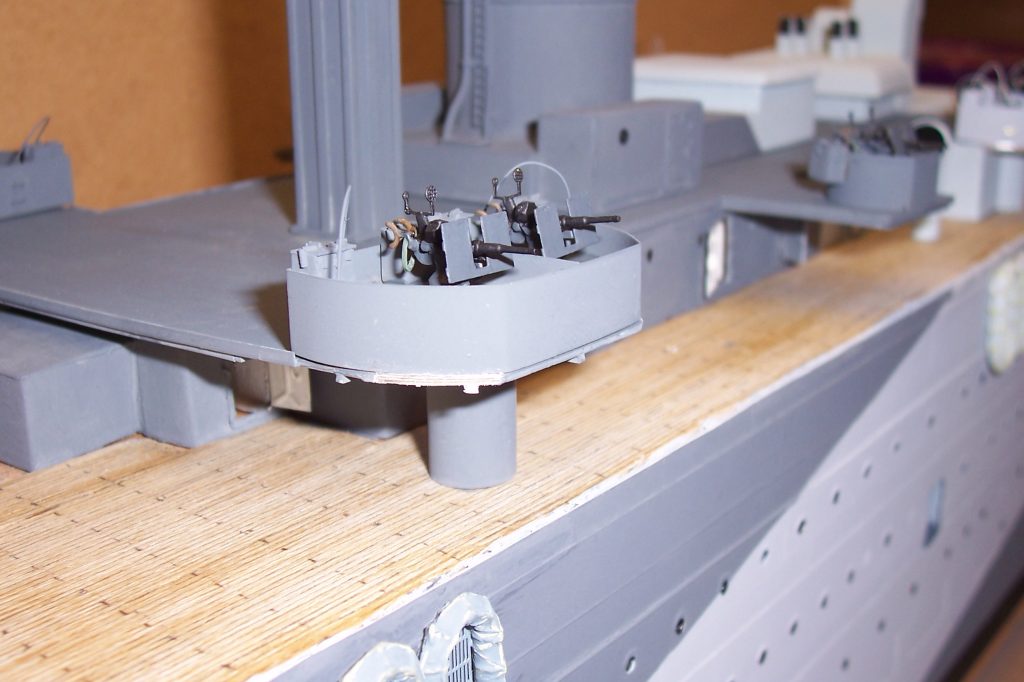
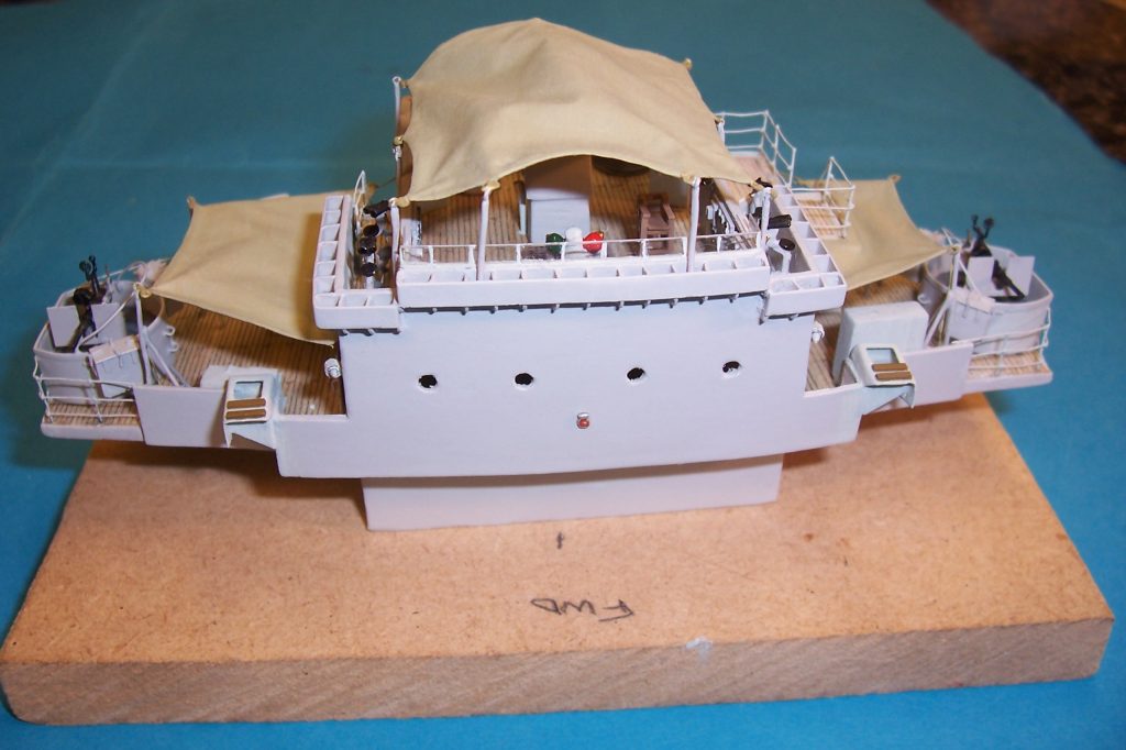
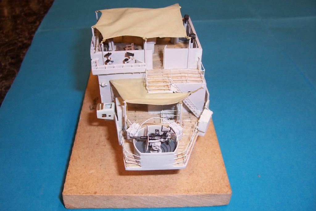
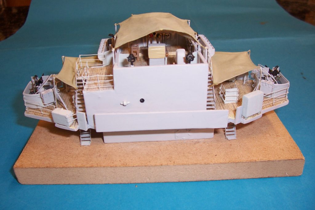
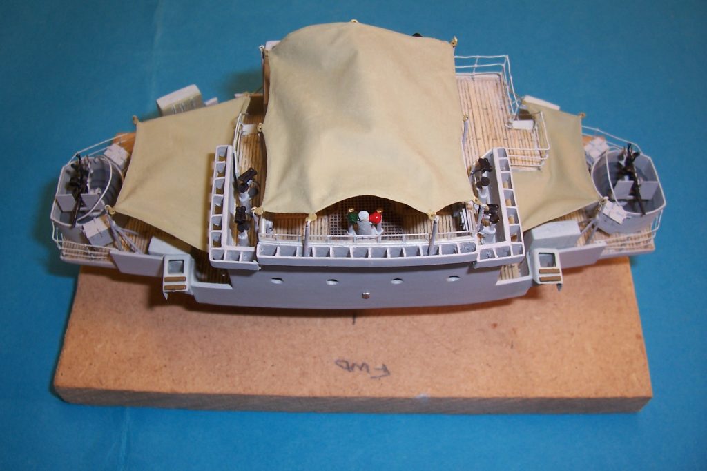
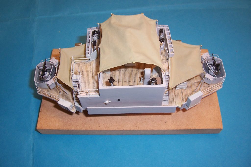
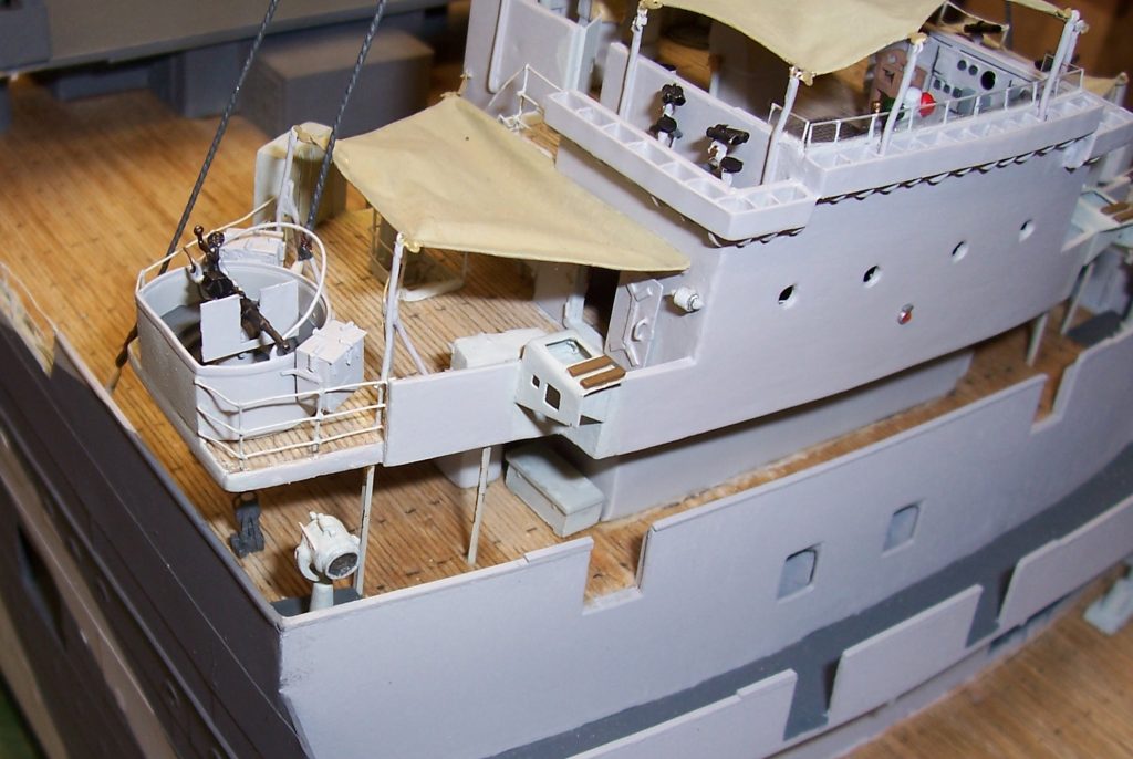
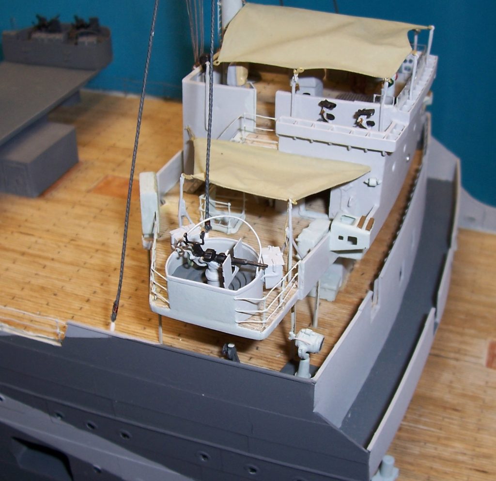
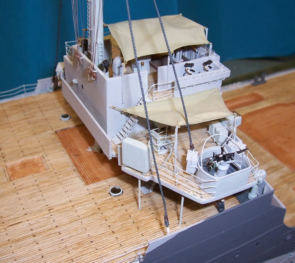
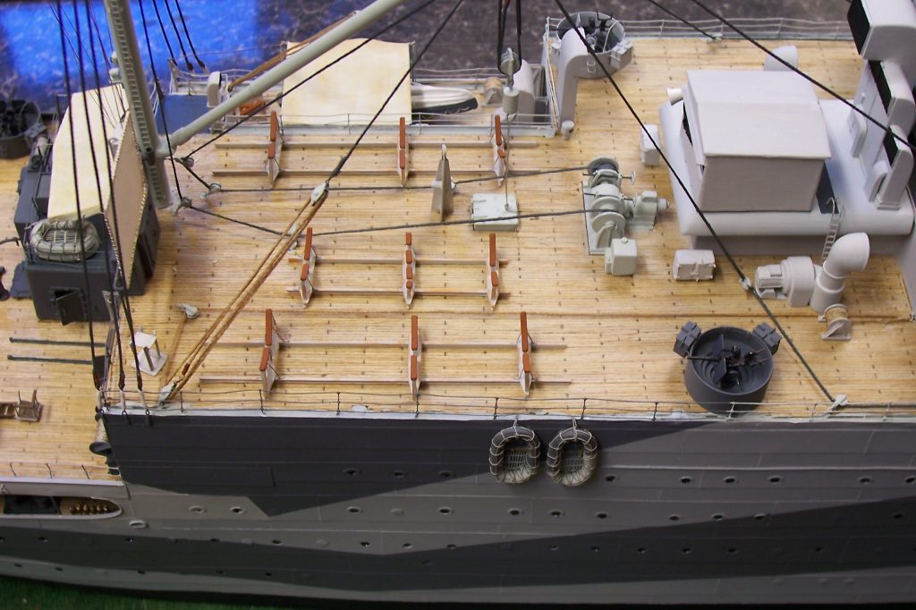
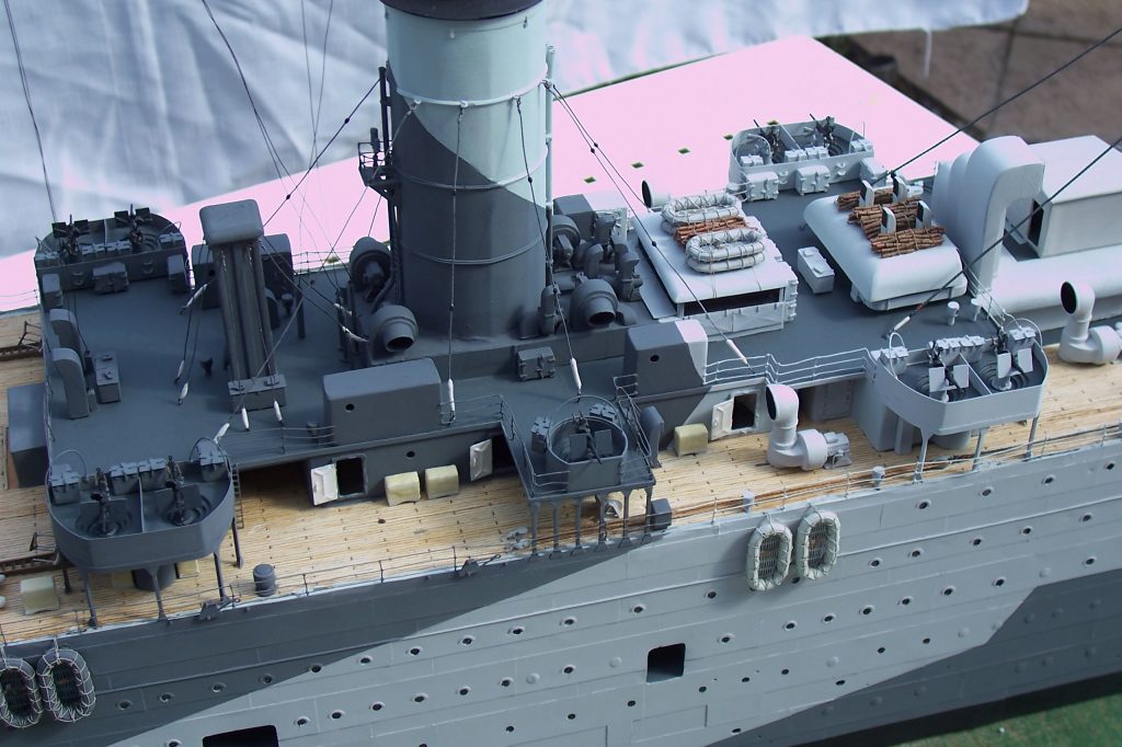
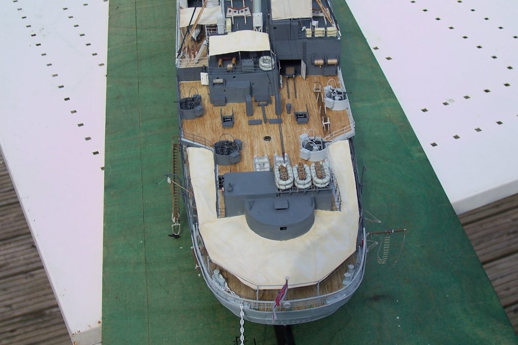
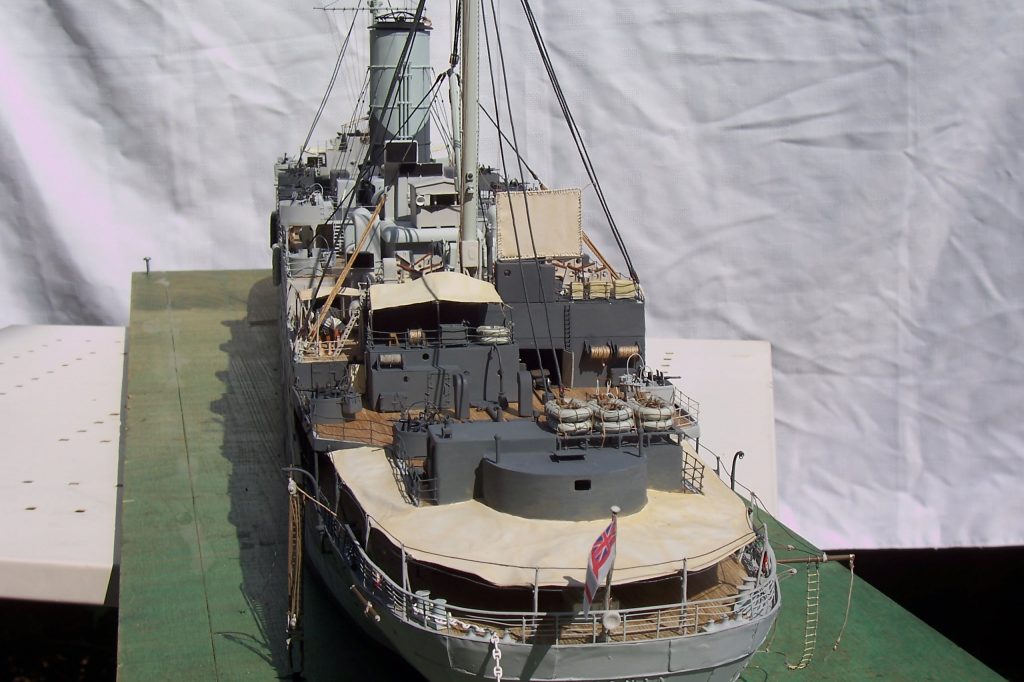
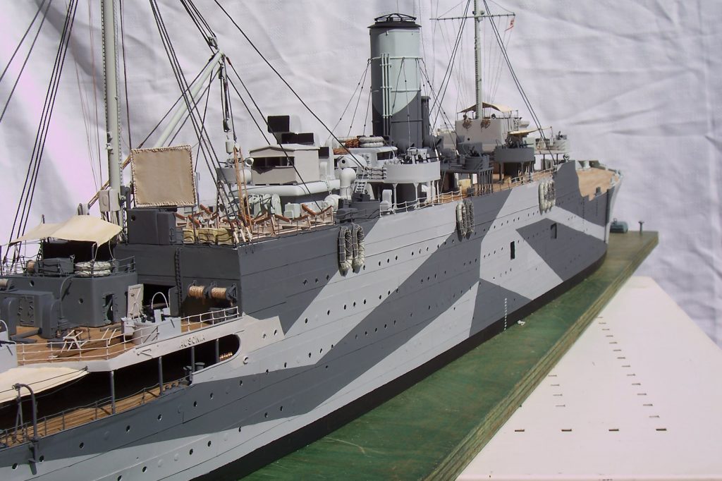
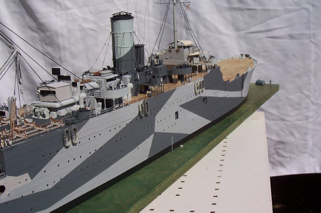
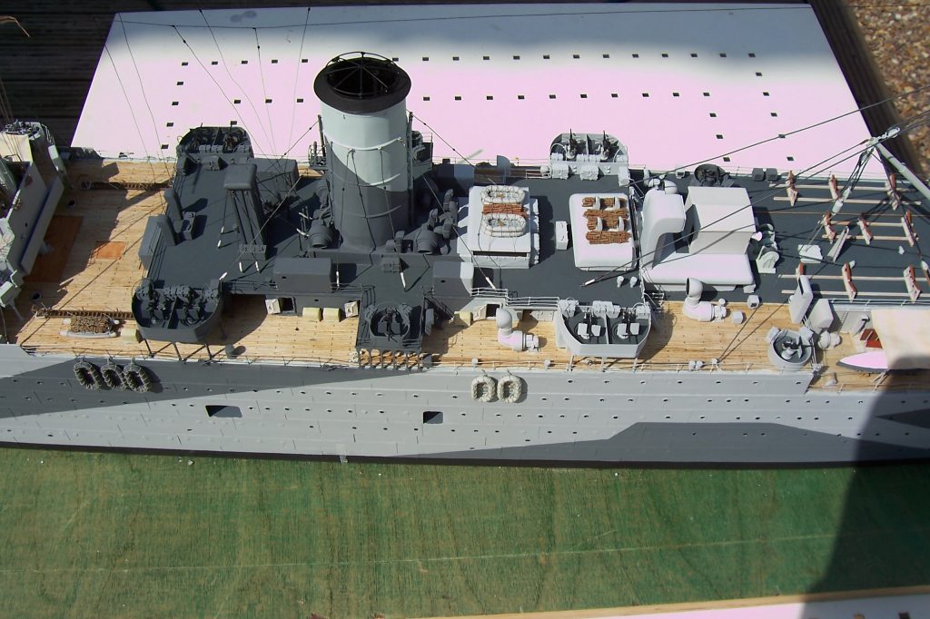
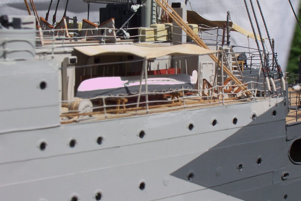
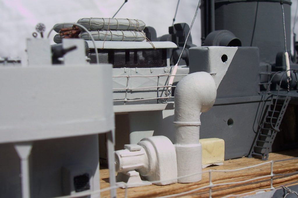
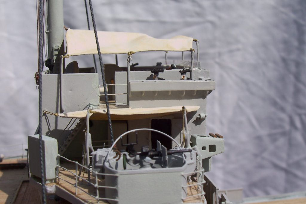
The 20mm gun tubs are fitted and the quarterdeck is nearing completion with just the sun screens to be added.
I will let the reader judge whether I have created an authentic representation of the ship.
I started manufacturing the ships cranes many years ago but had to stop as I could find very few details regarding the machinery and their control mechanism except for that shown in the plans. With the addition of several photographs showing one of the foredeck cranes, these can be completed.
Currently under construction is the bridge and wheel house assembly.
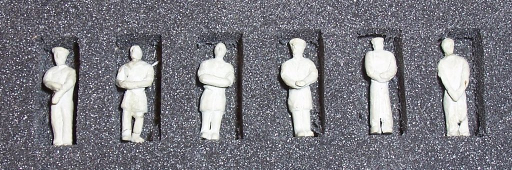
I had an attempt at making a few crew members for the model. These were carved from modelling clay formed around a wire support but at just under 15mm high, proved a bit of a challenge.
I was a long time member of the Surface Warship Association, which is a group dedicated to the modelling of warships and in 1998, attended the London Model Show at Pickets Lock on their behalf. Along with my model of a Royal Navy minesweeper, I took my partially completed Ausonia model. Much to the announce of my fellow modellers, this seemed to generate more interest than any other model at the show and even got a mention in the Surface Warship Association magazine “Quarterdeck Ramblings”.
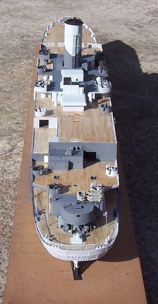
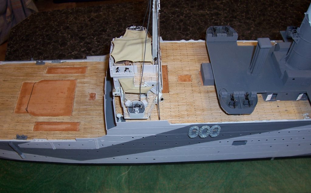
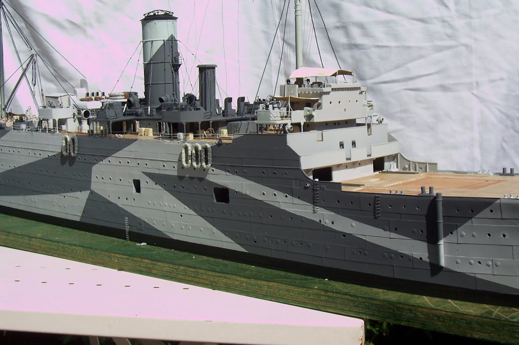
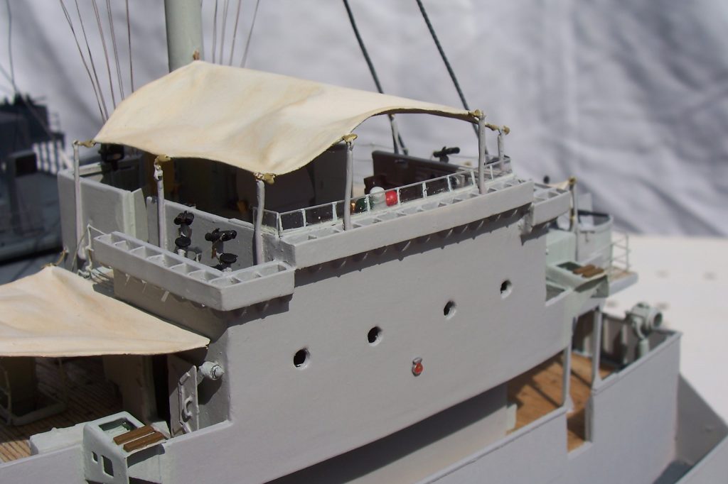
The bridge and wheel house assembly is now complete.
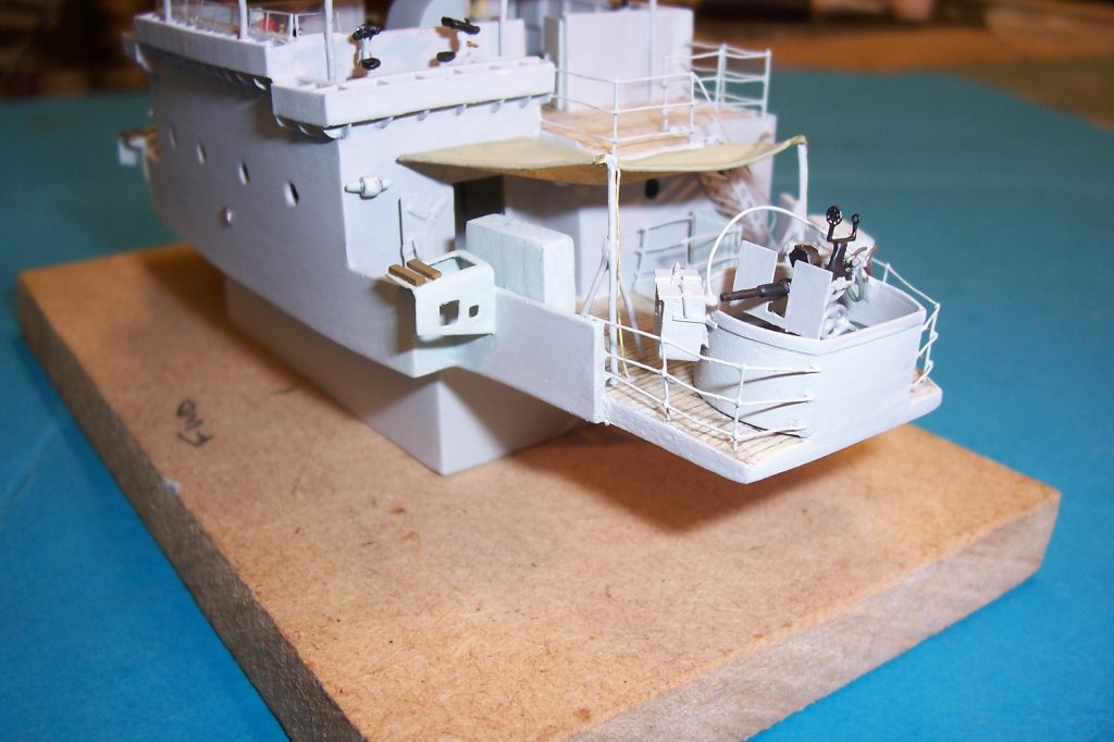
The bridge and wheel house assembly fitted.
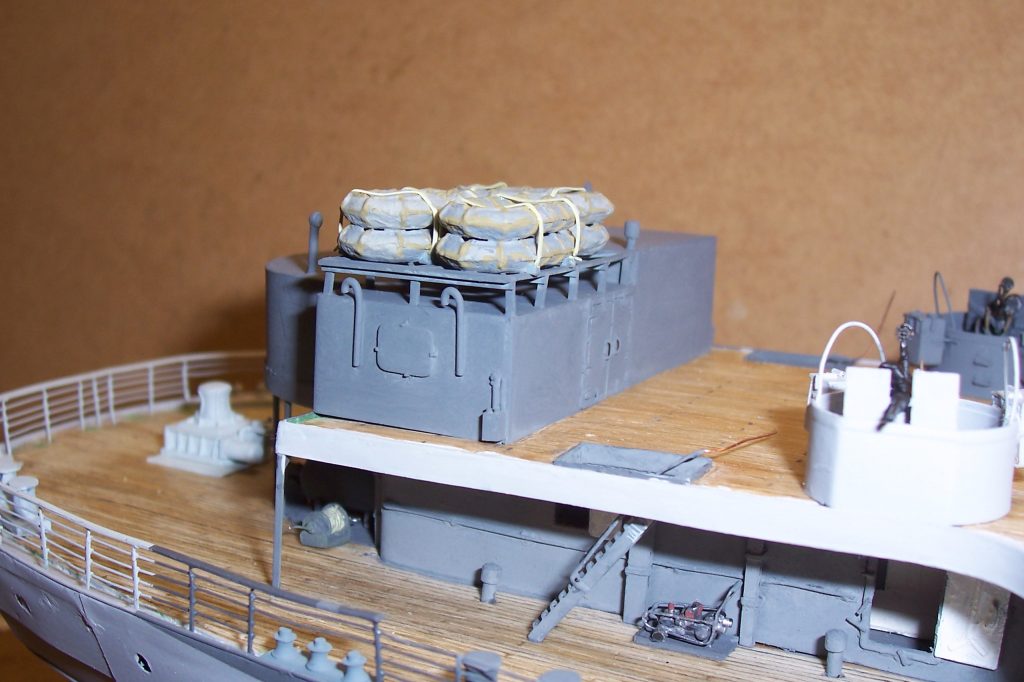
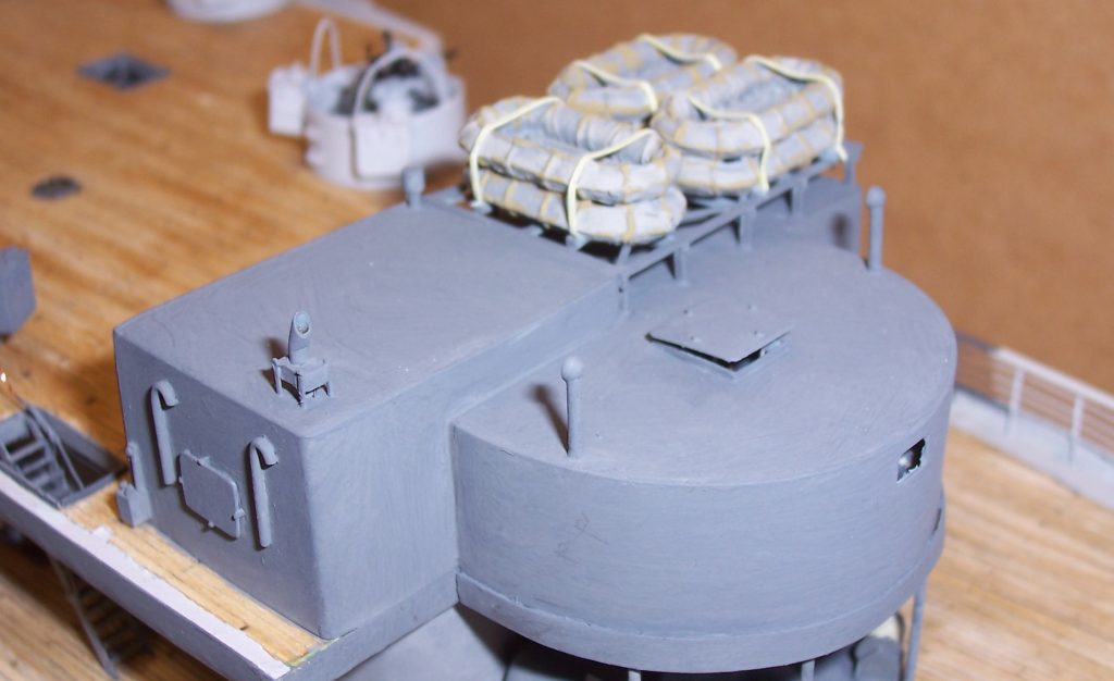
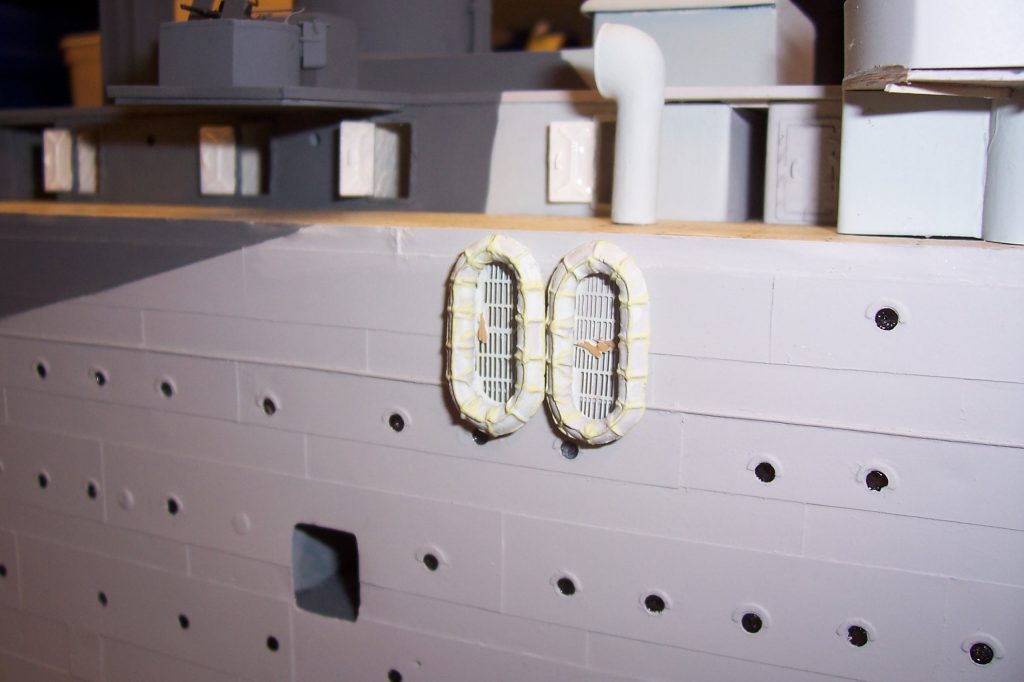
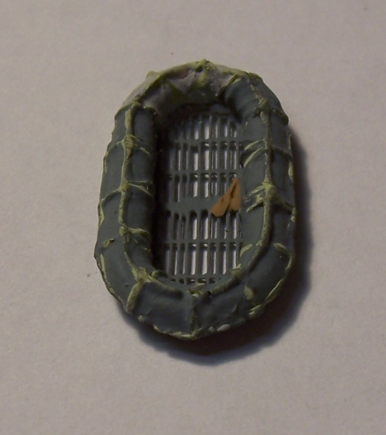
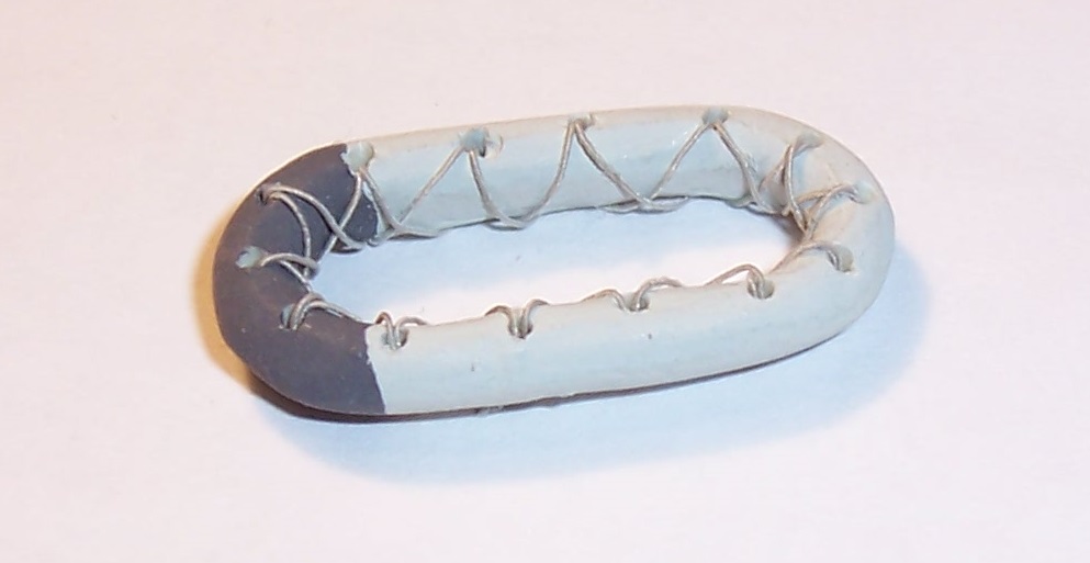
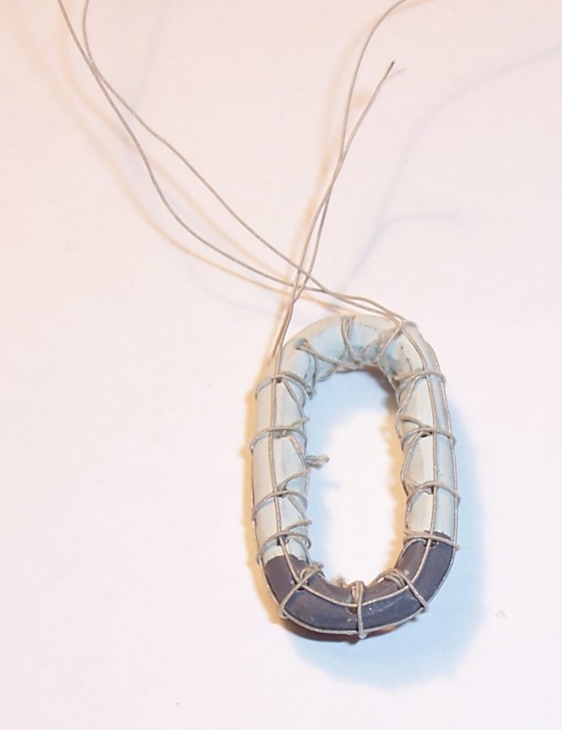
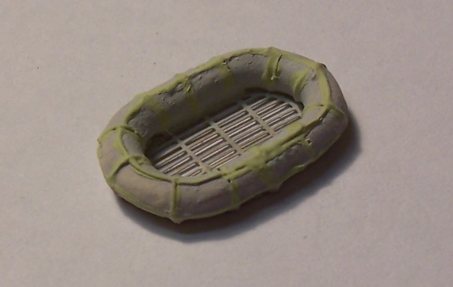
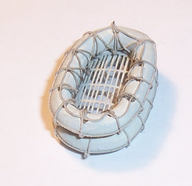
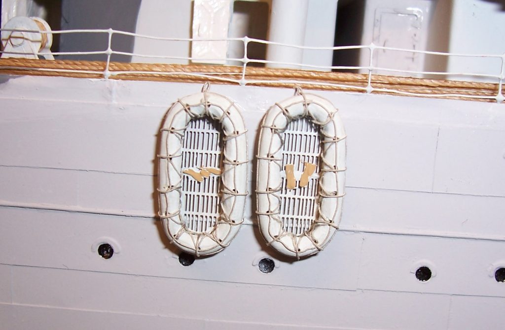
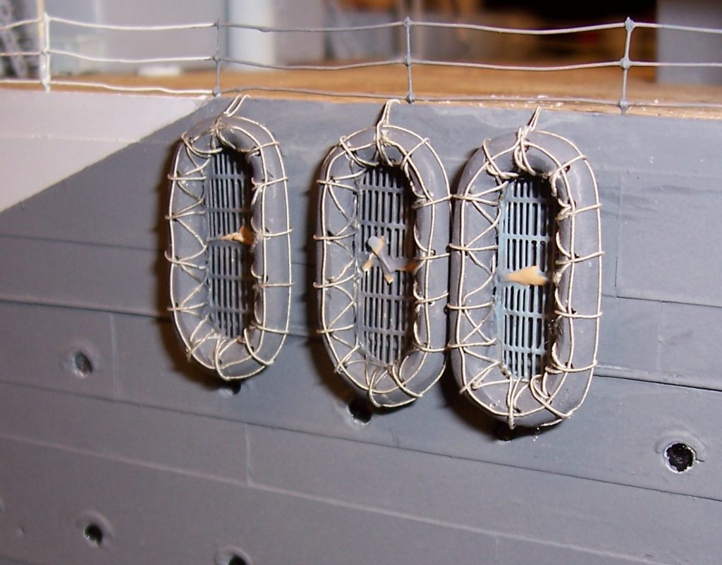
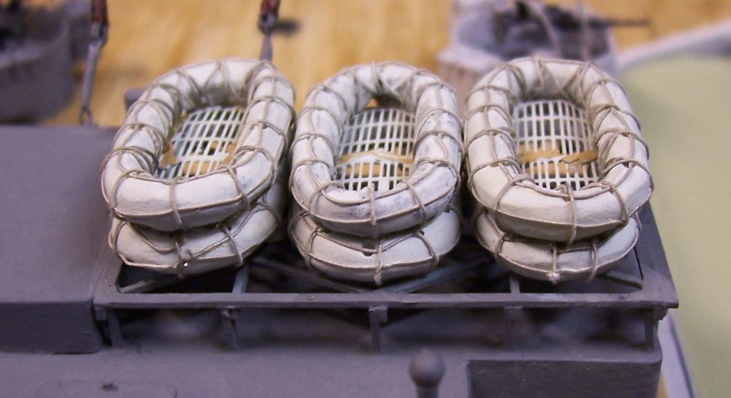
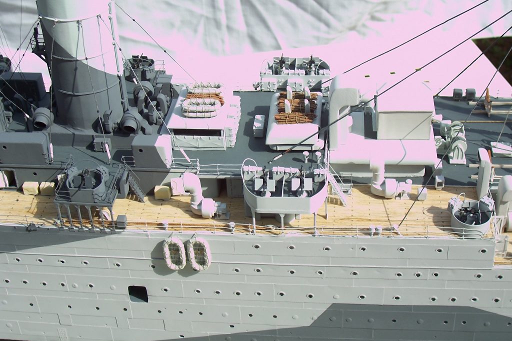
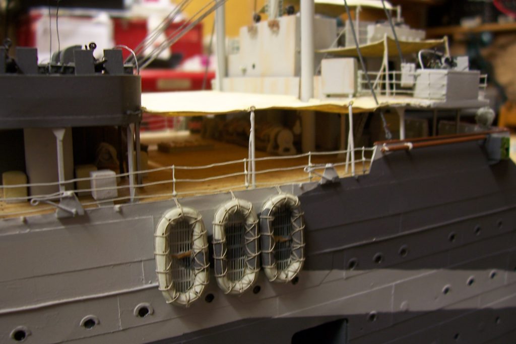
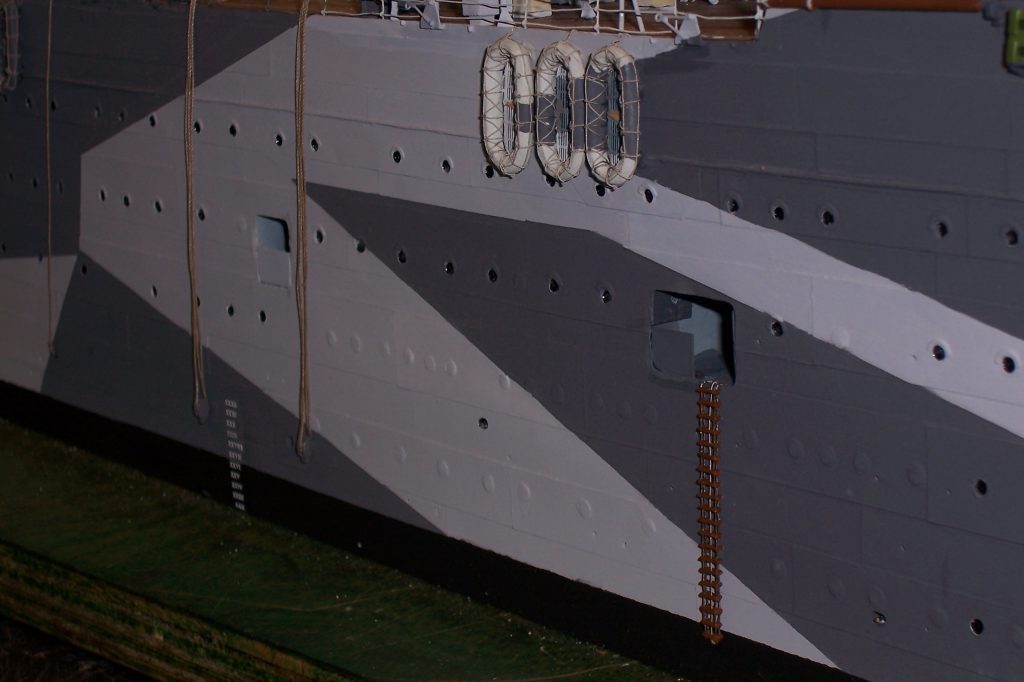
Several years ago I purchased commercially available resin Carely floats as I thought that it would save build time but had never really been happy with the results. In 2016 I decided to remove these from the model and add the rope work to the sides. The following photos show some of this construction process for the large Carely floats.
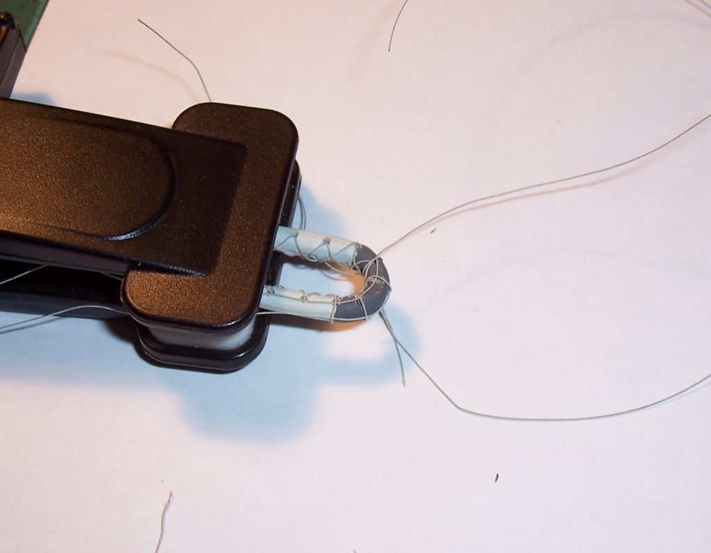
The process was identical for the smaller Carely floats.
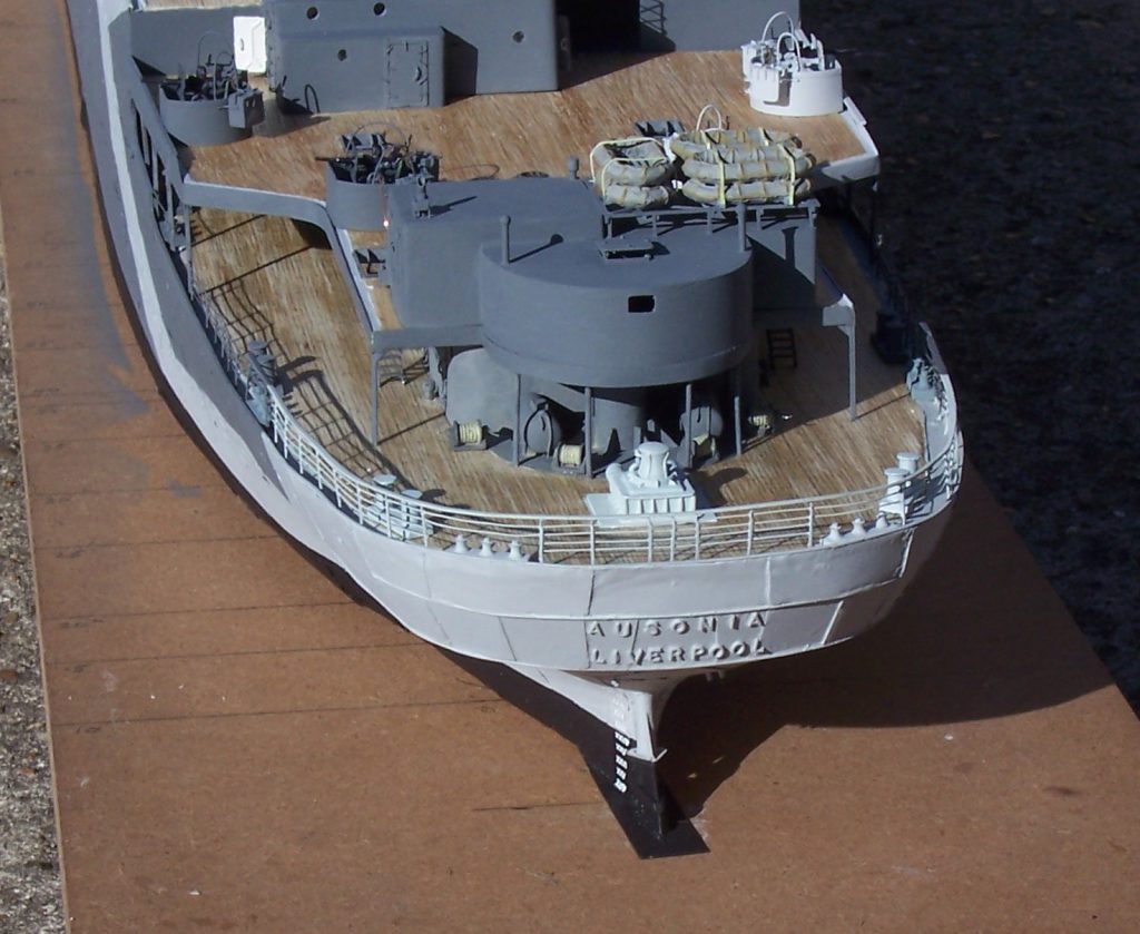
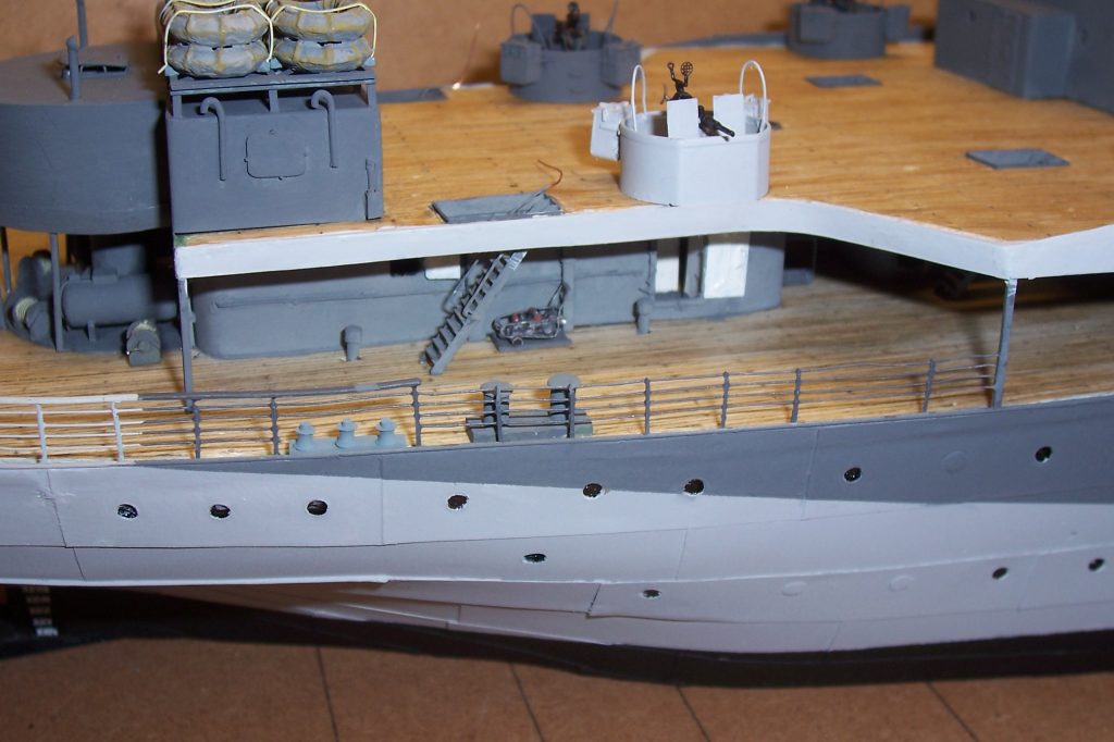
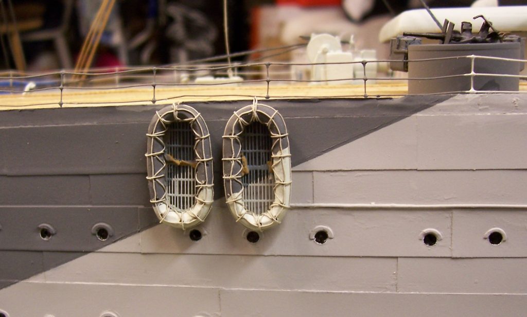
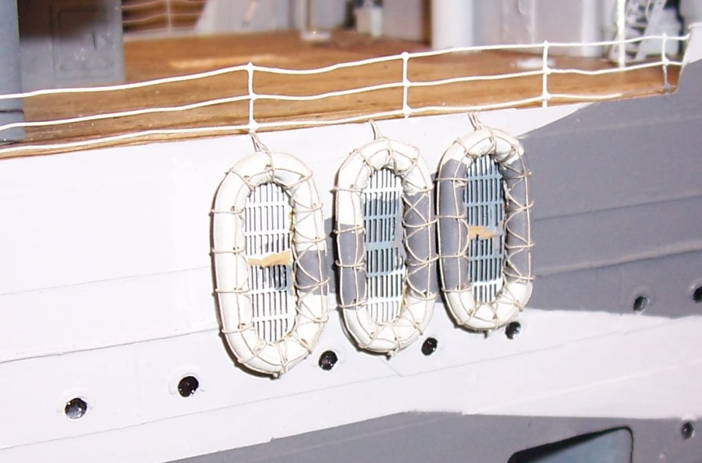
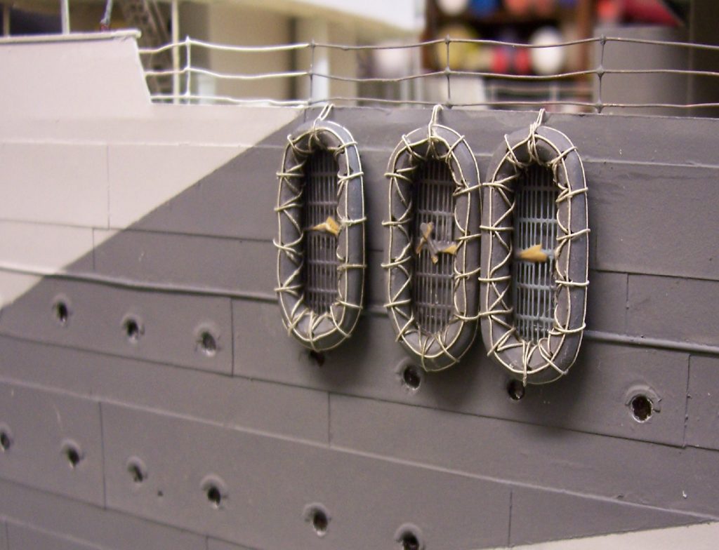
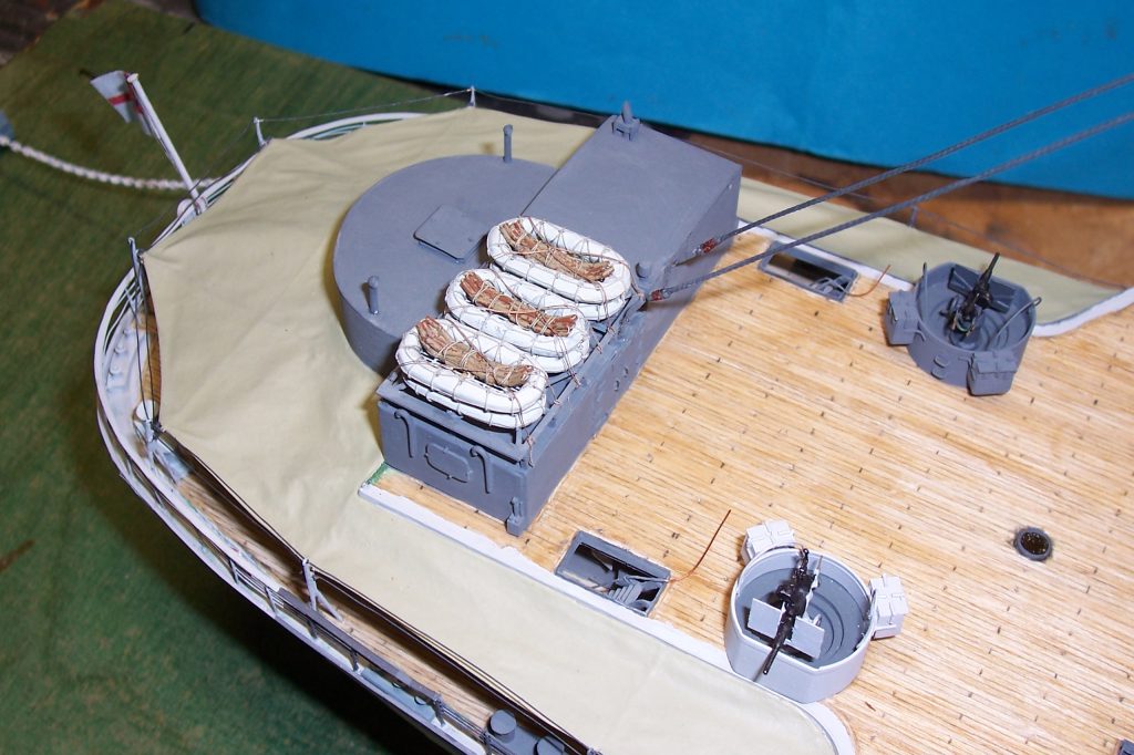
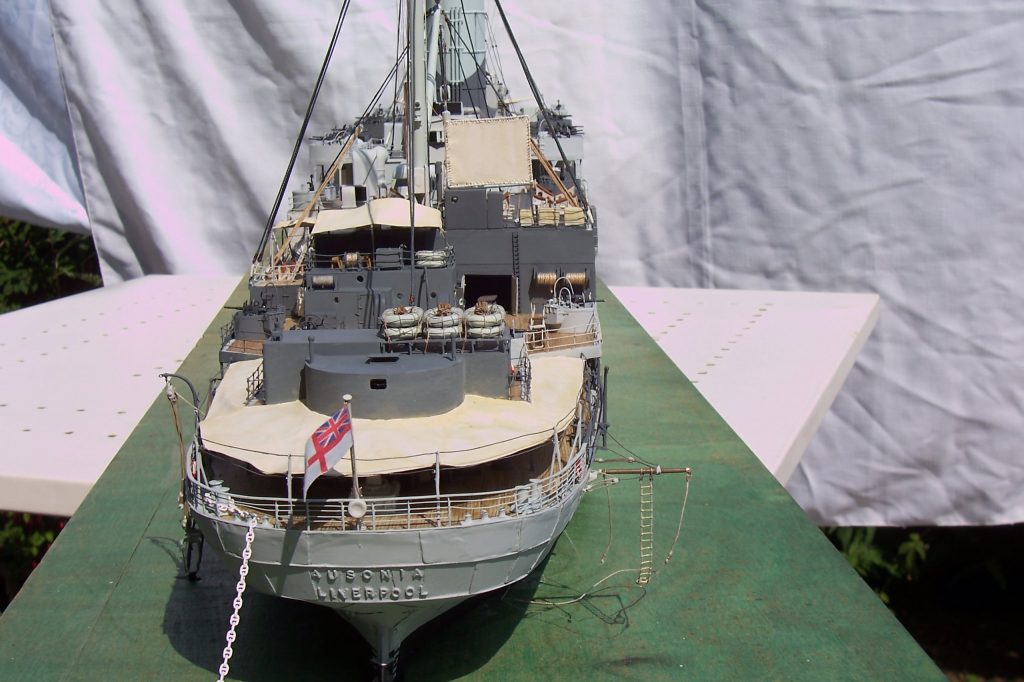
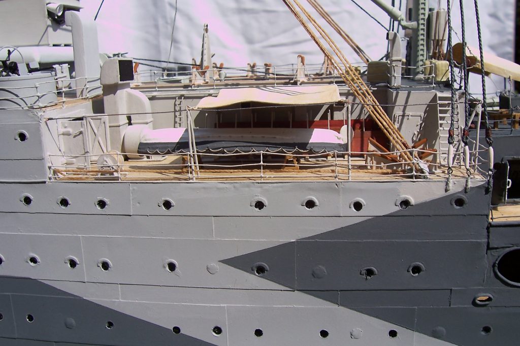
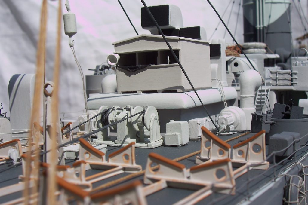
The following photographs show my modified Carely floats fitted to the model.
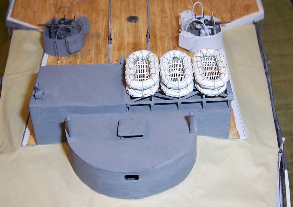
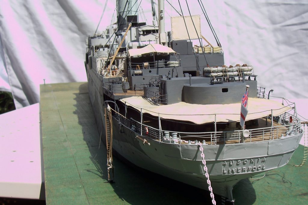
Cork floatation sticks have been added to the Carely floats on the stern.
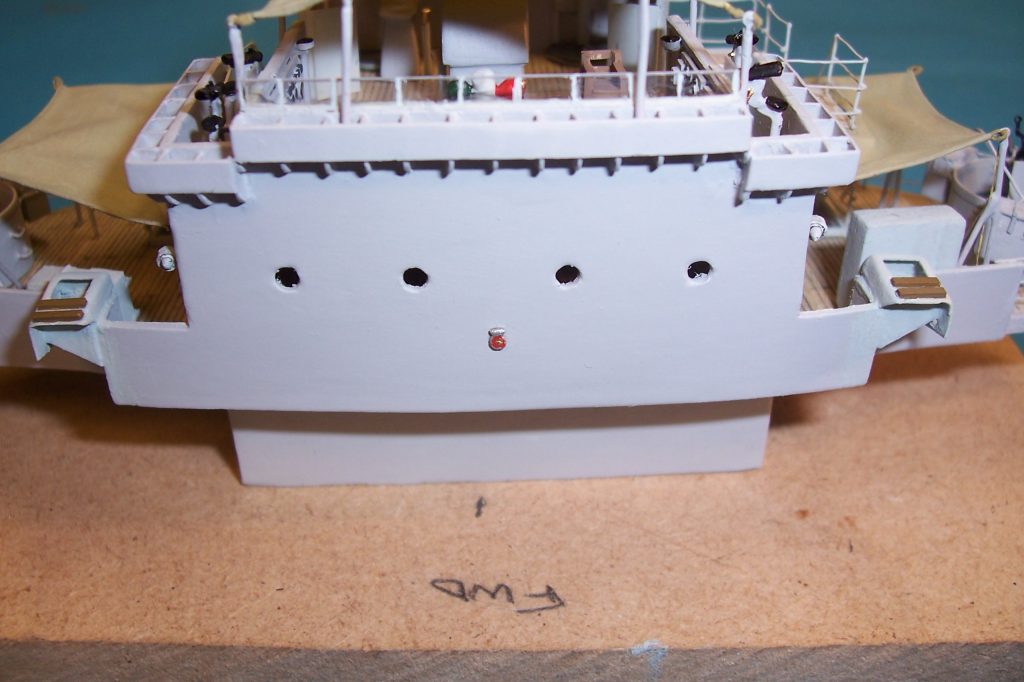
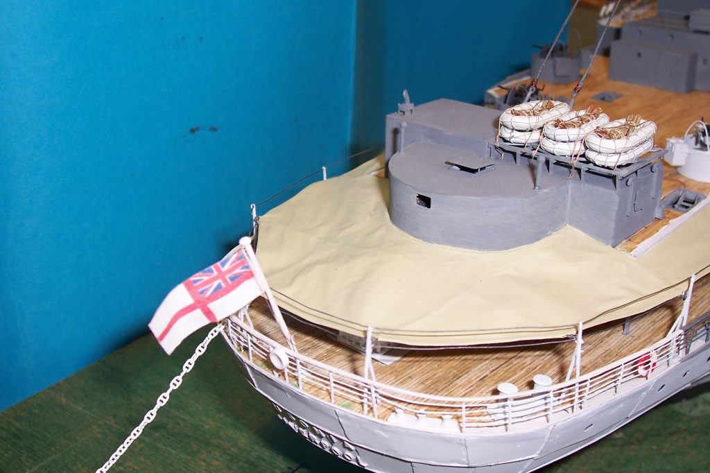
The completed bridge structure has been installed along with deck fittings.
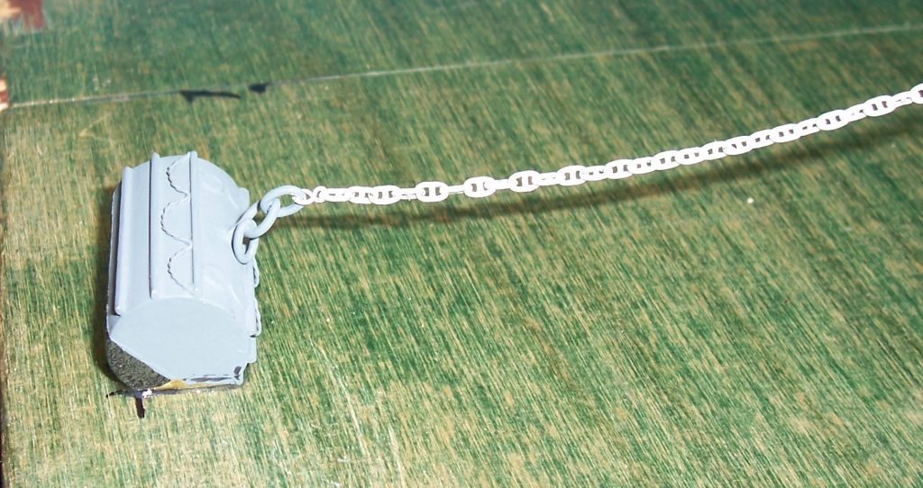
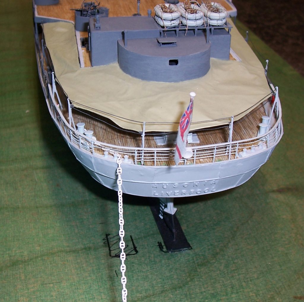
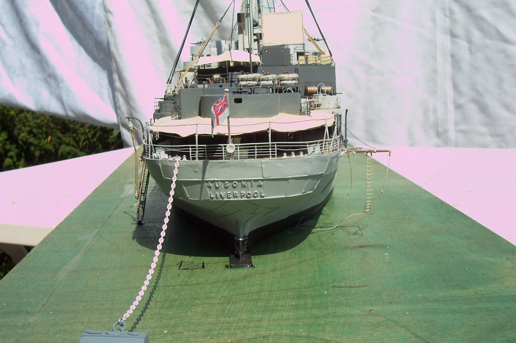
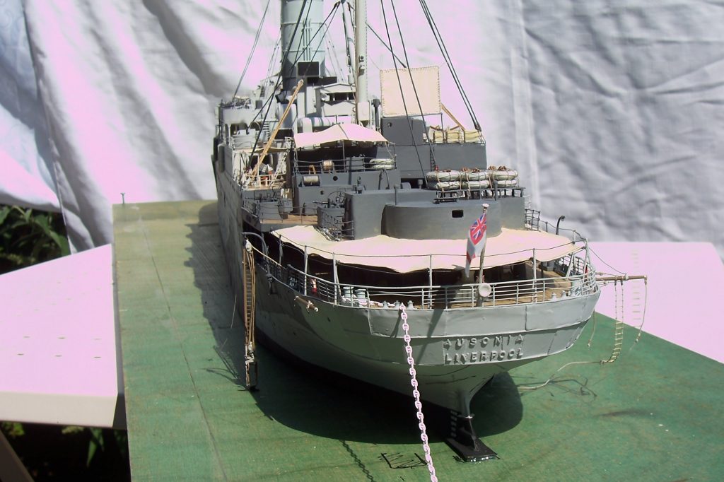
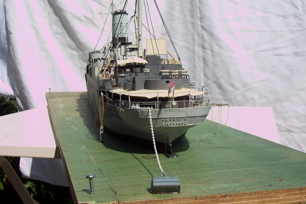
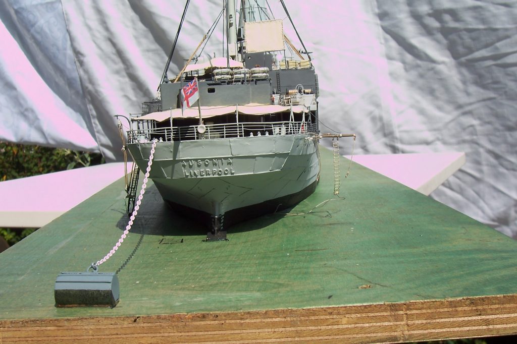
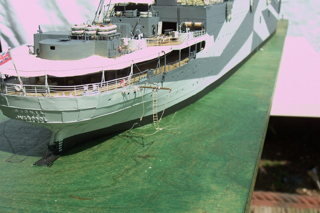
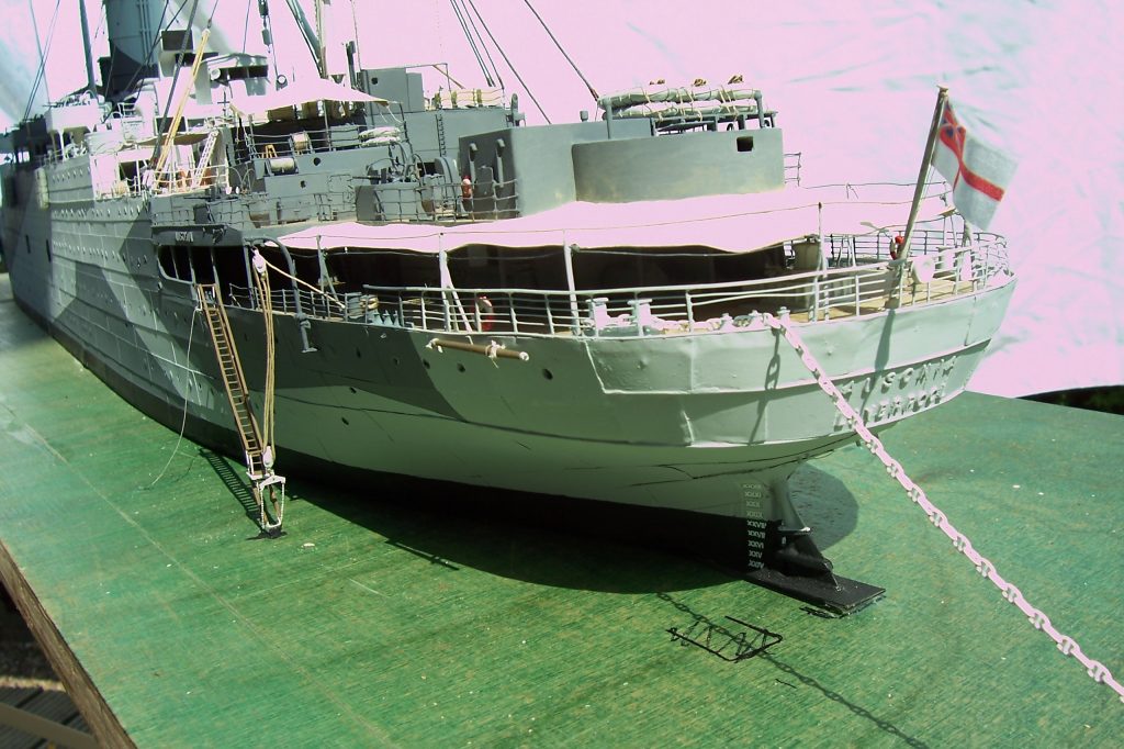
The stern buoy and anchor chain has been made and installed.
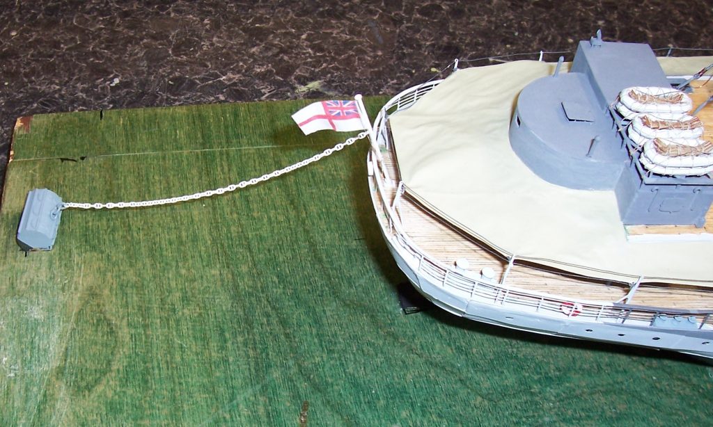
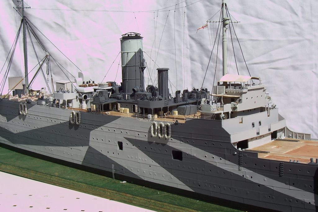
The ensign on the stern.
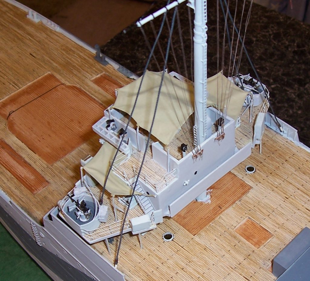
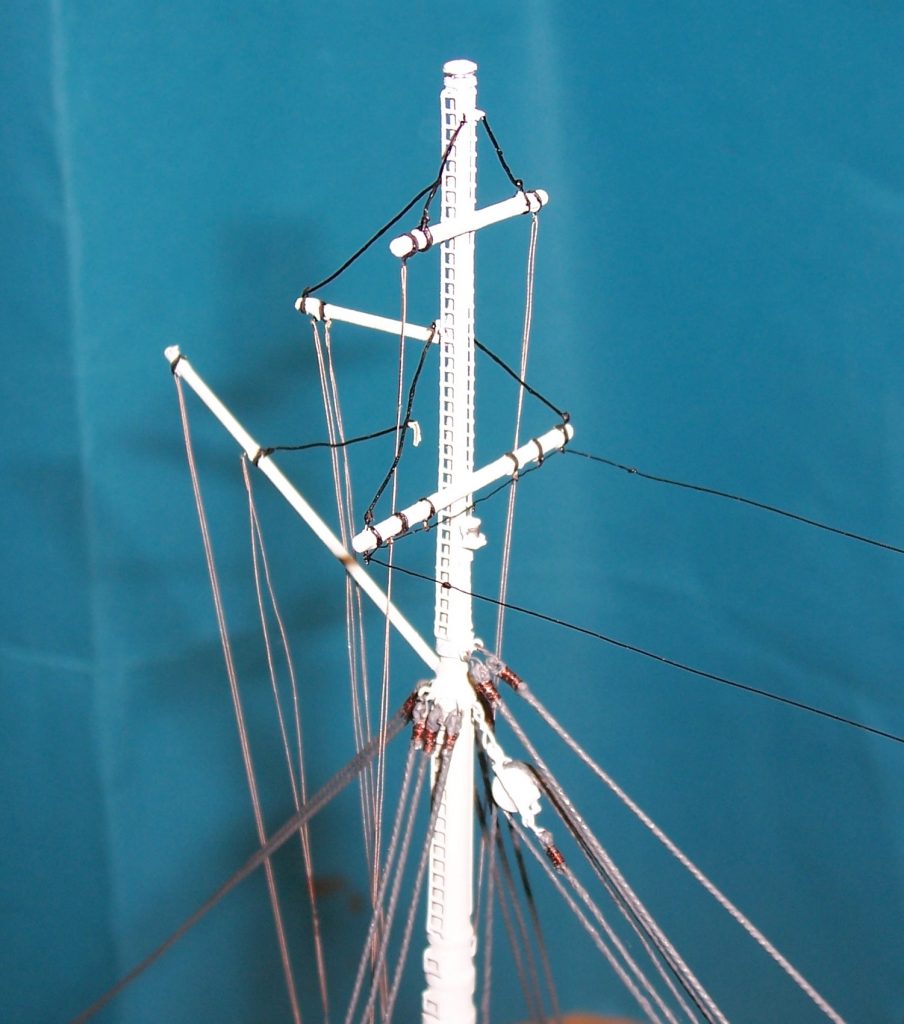
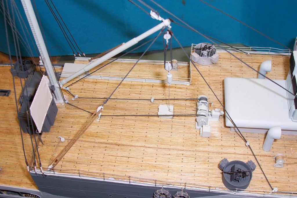
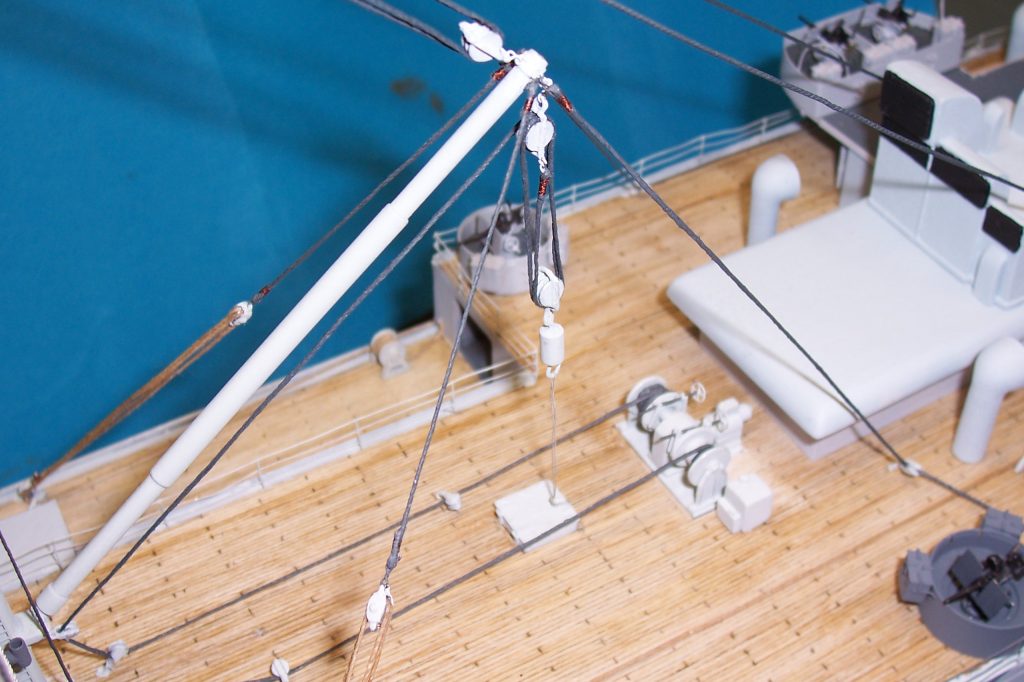
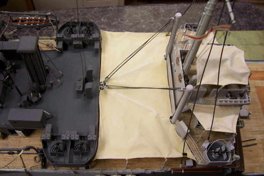
The rear mast and rigging now fitted.
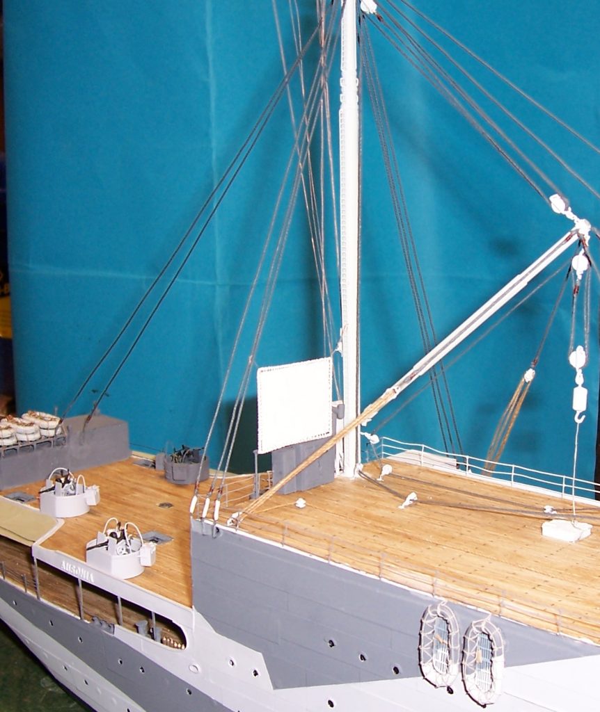
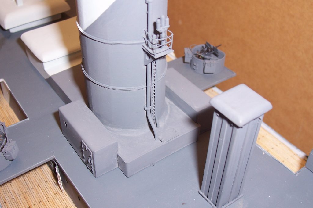
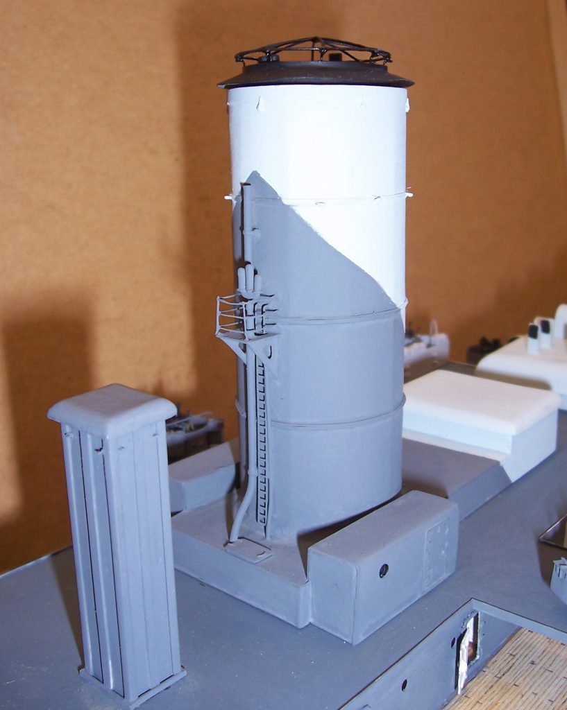
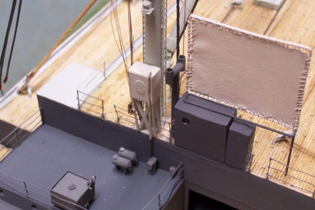
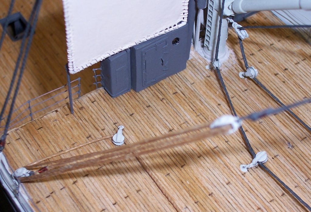
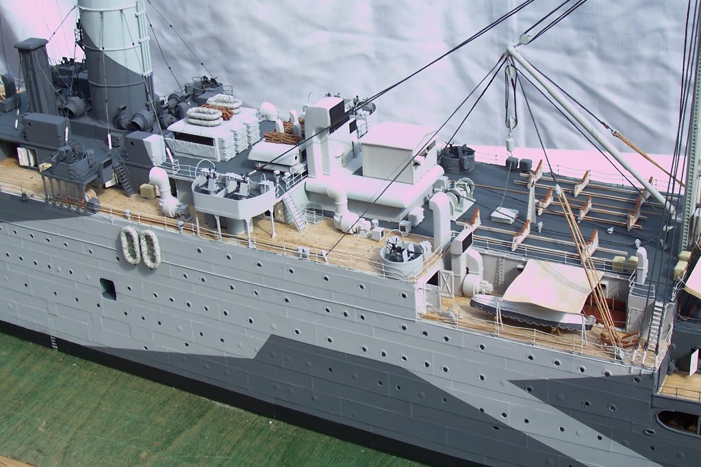
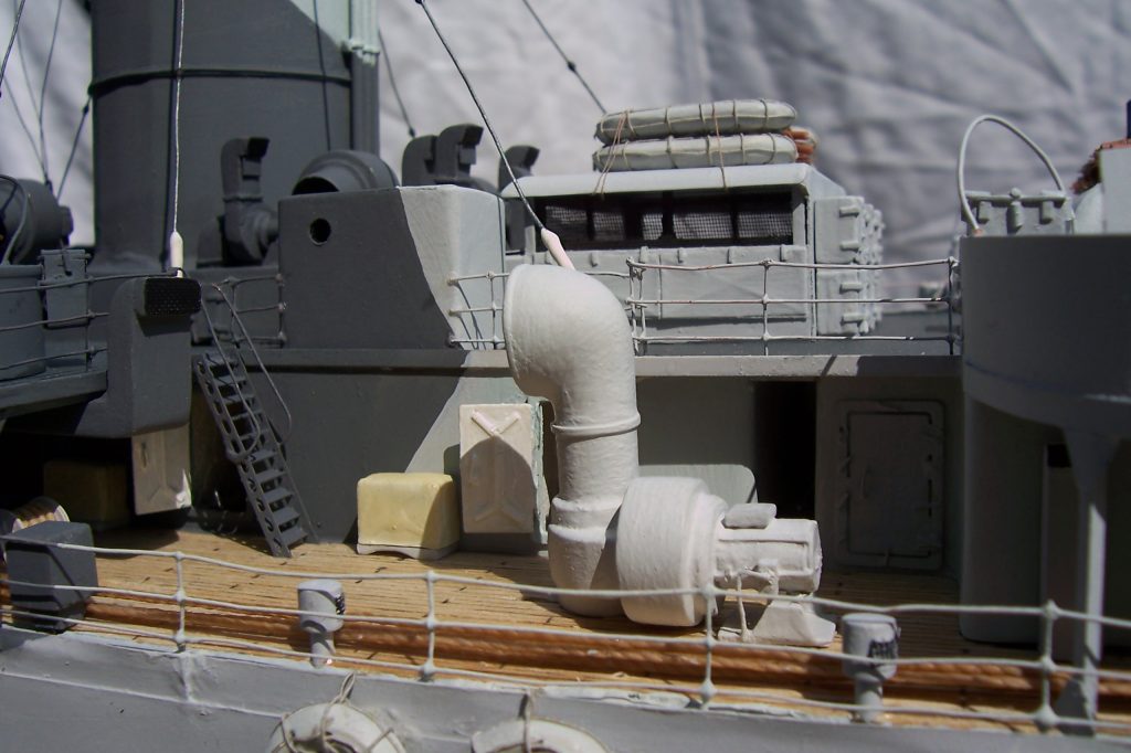
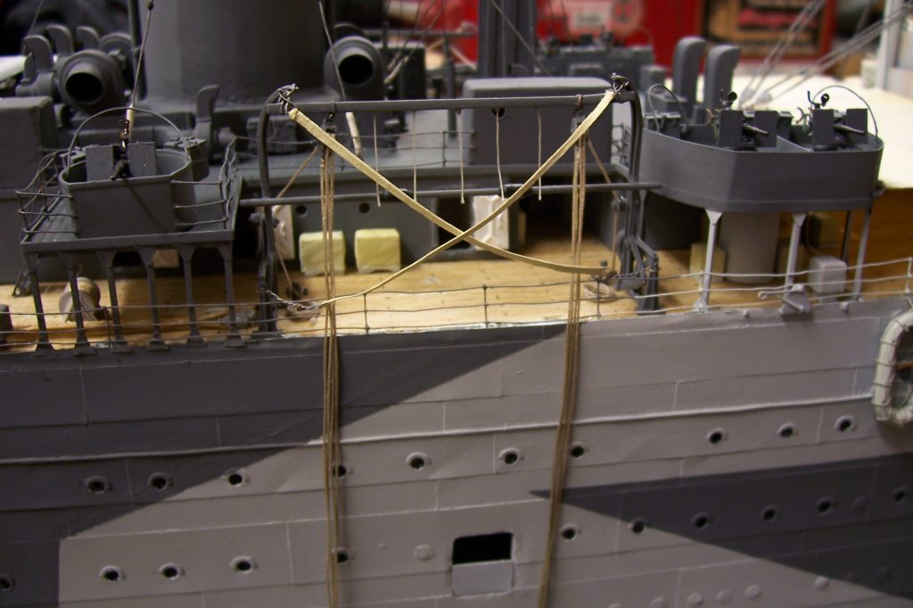
The canvas screen at the bottom of the mast onto which films were projected.
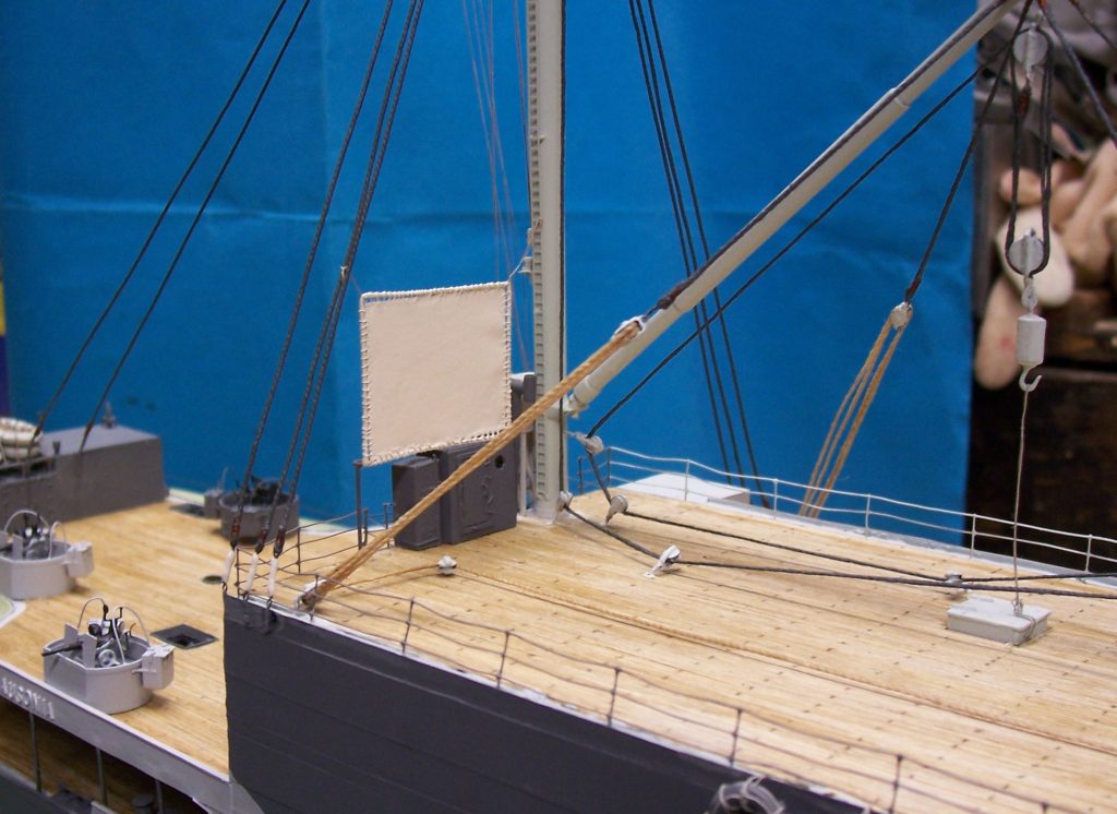
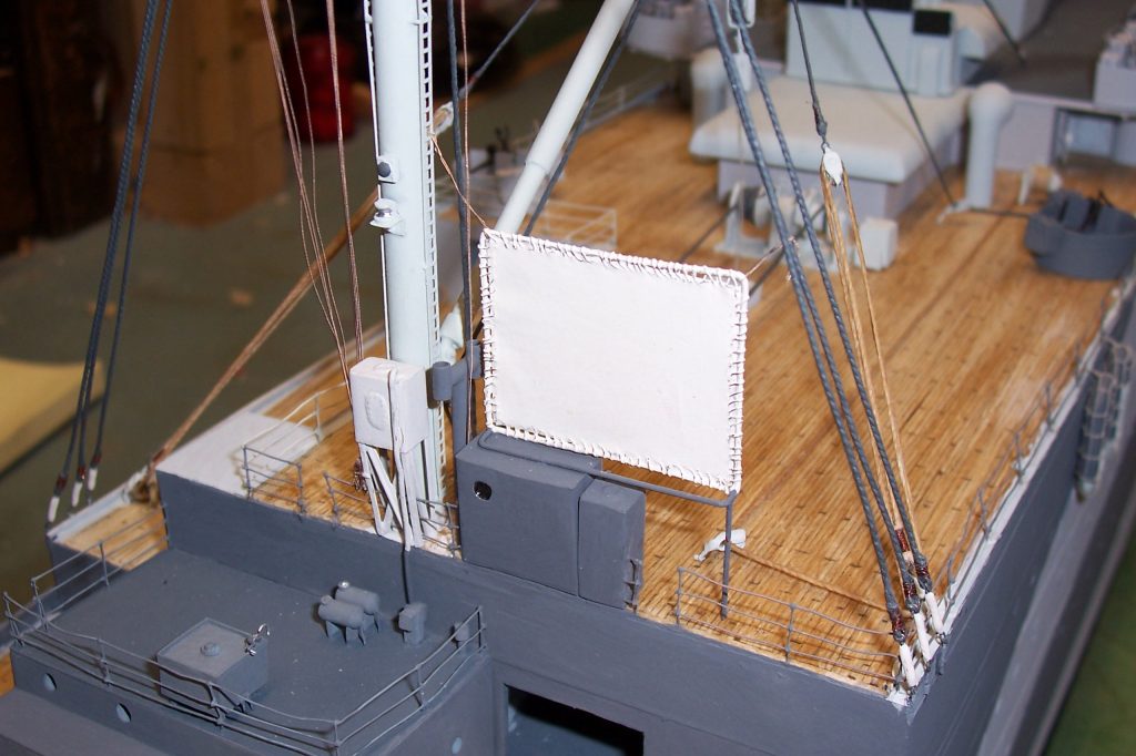
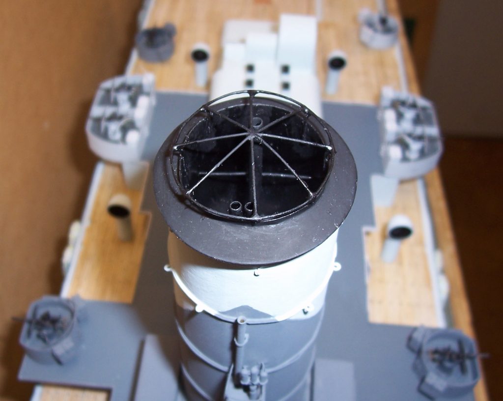
The water tank at the bottom of the rear mast.
The rear mast rigging.
March 2018
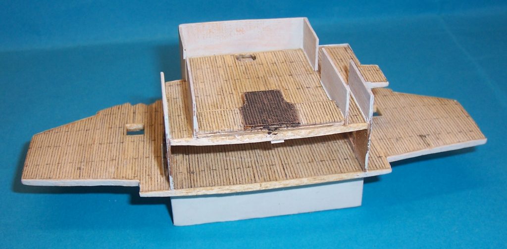
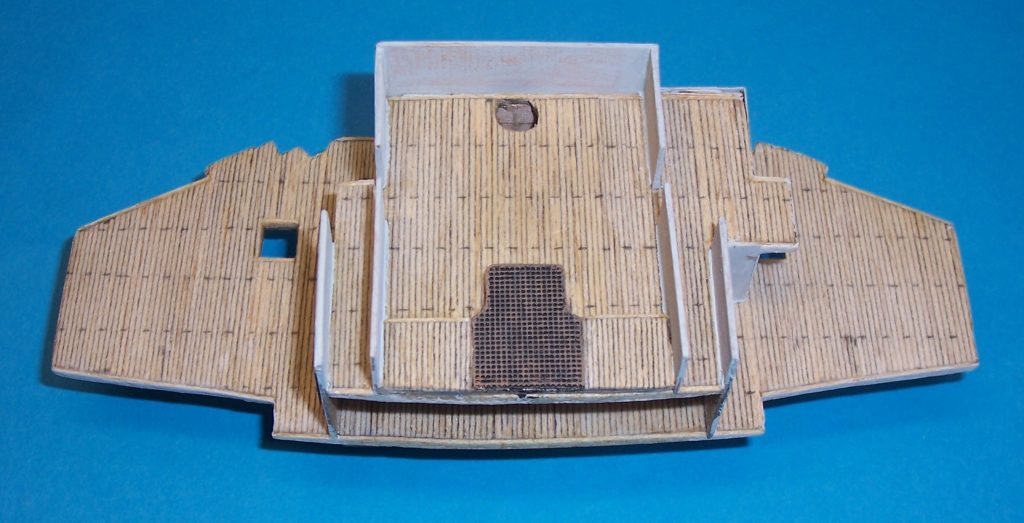
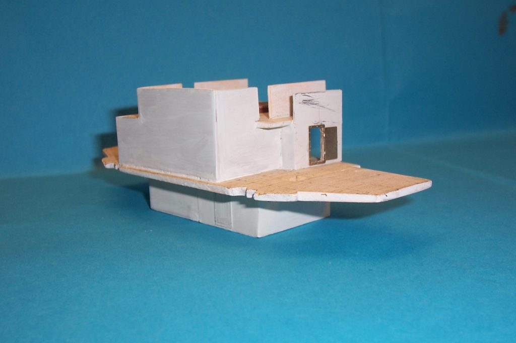
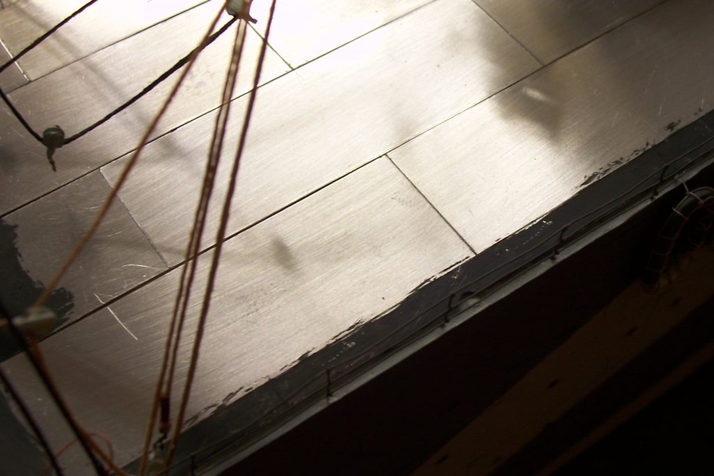
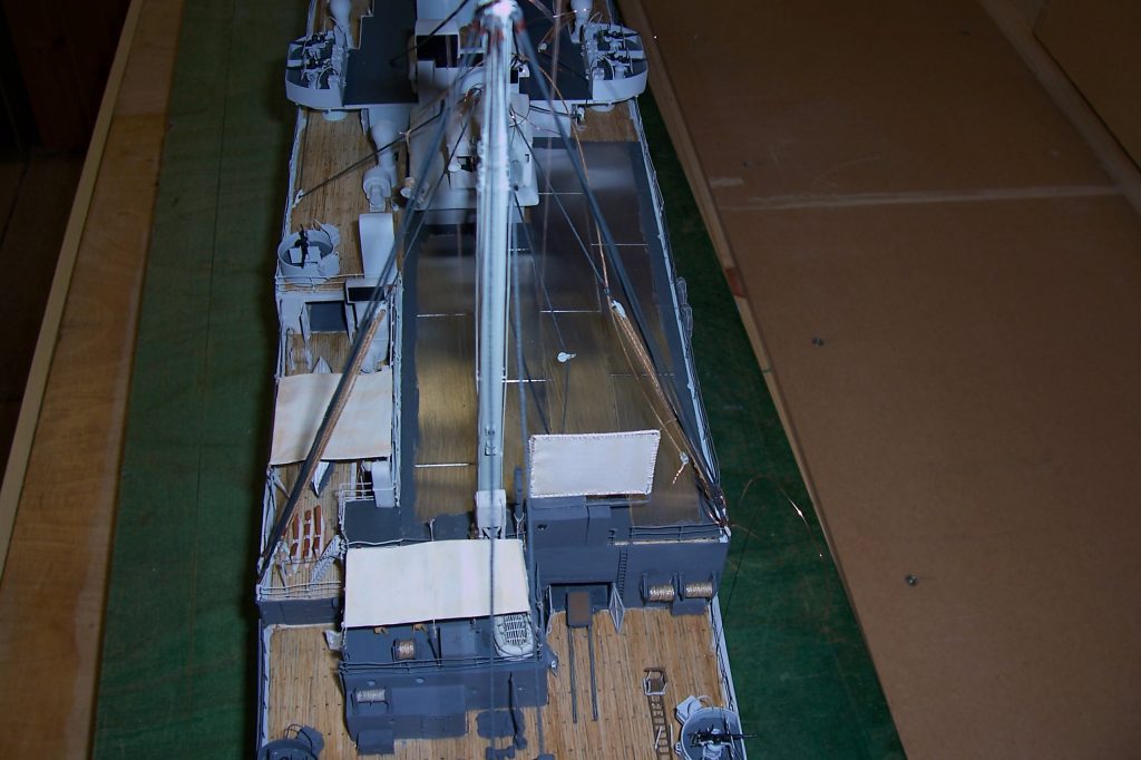
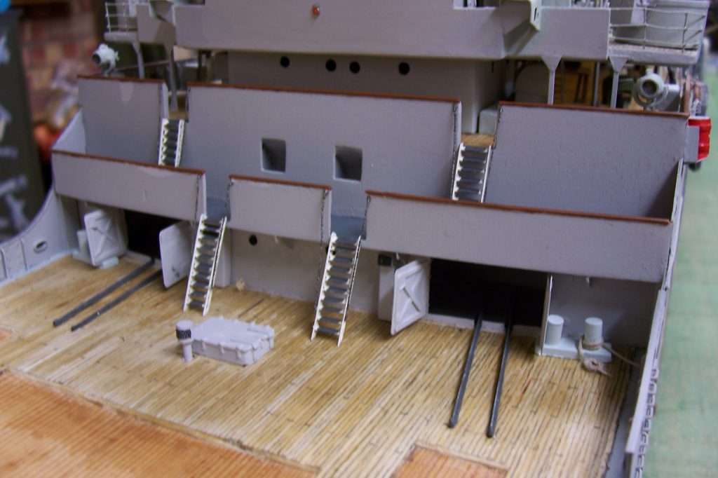
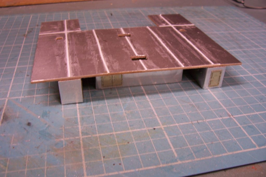
Having just completed the rear boat deck, new photographic evidence came to light which showed that a good portion of this deck was not in fact timber planks, but steel deck plates. The reason for this was that during the ships conversion to a repair ship during 1943, a large section of the upper deck had to be cut away to enable the heavy plate shop machinery to be lowered and installed into the deck below. To allow installation of the 2 ton overhead traveller crane in the roof of plate shop, this area of the boat deck had to be raised by several inches.
The completed rear boat deck as it was in 2017.
The cradles for the ships boats and all the other fittings in the affected area had to be removed and the deck plates, made from aluminium sheet, were then laid on top of the existing planks. Once painted, the fittings were refitted.
2018 Update
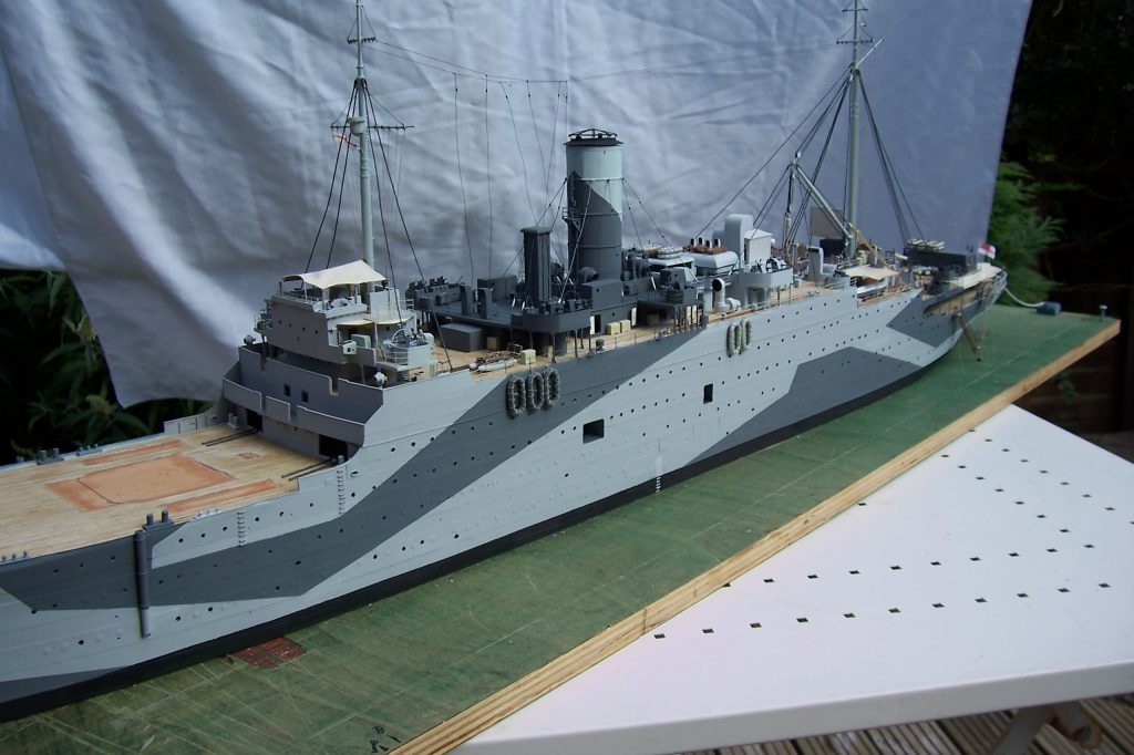
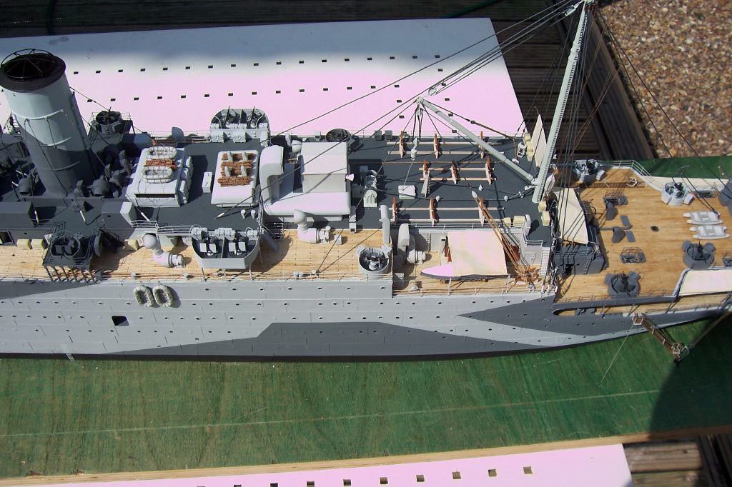
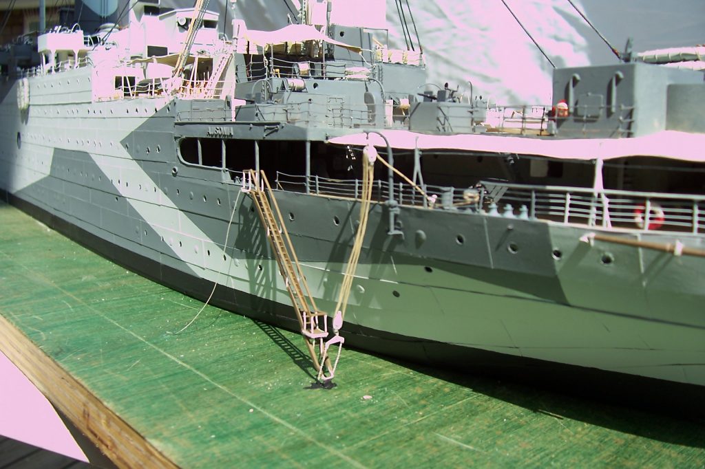
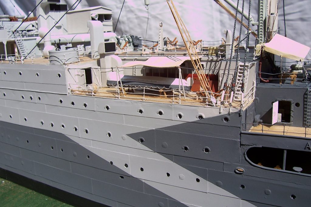
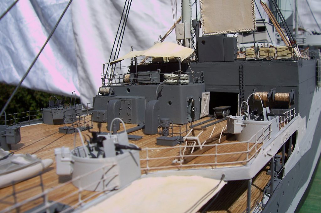
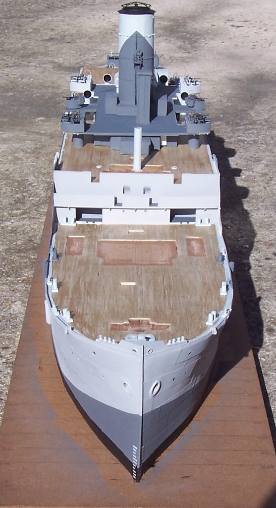
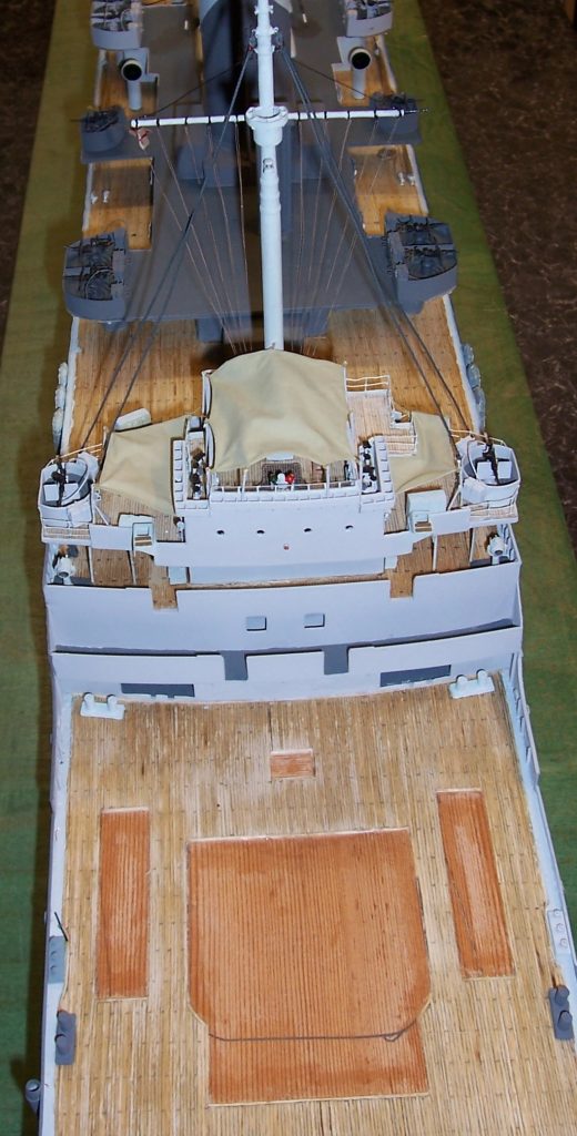
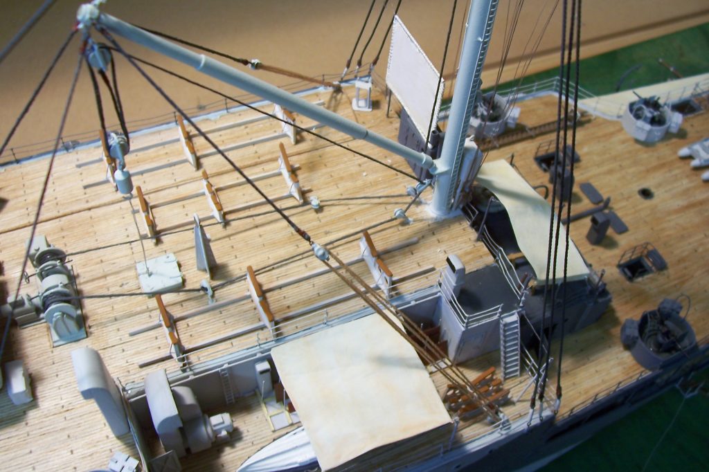
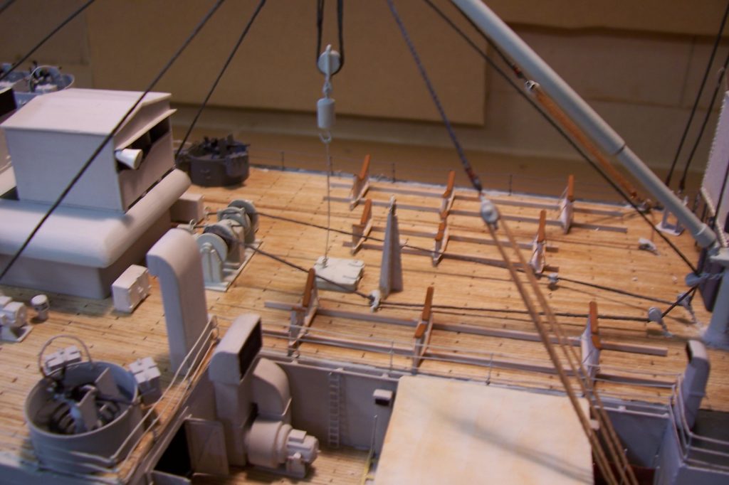
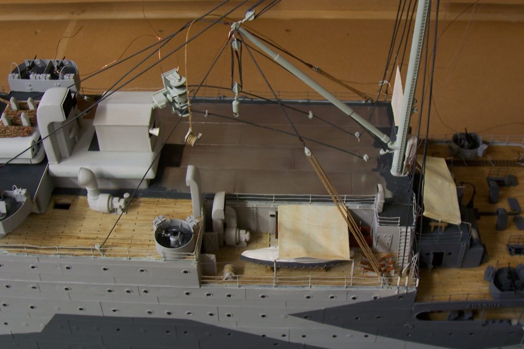
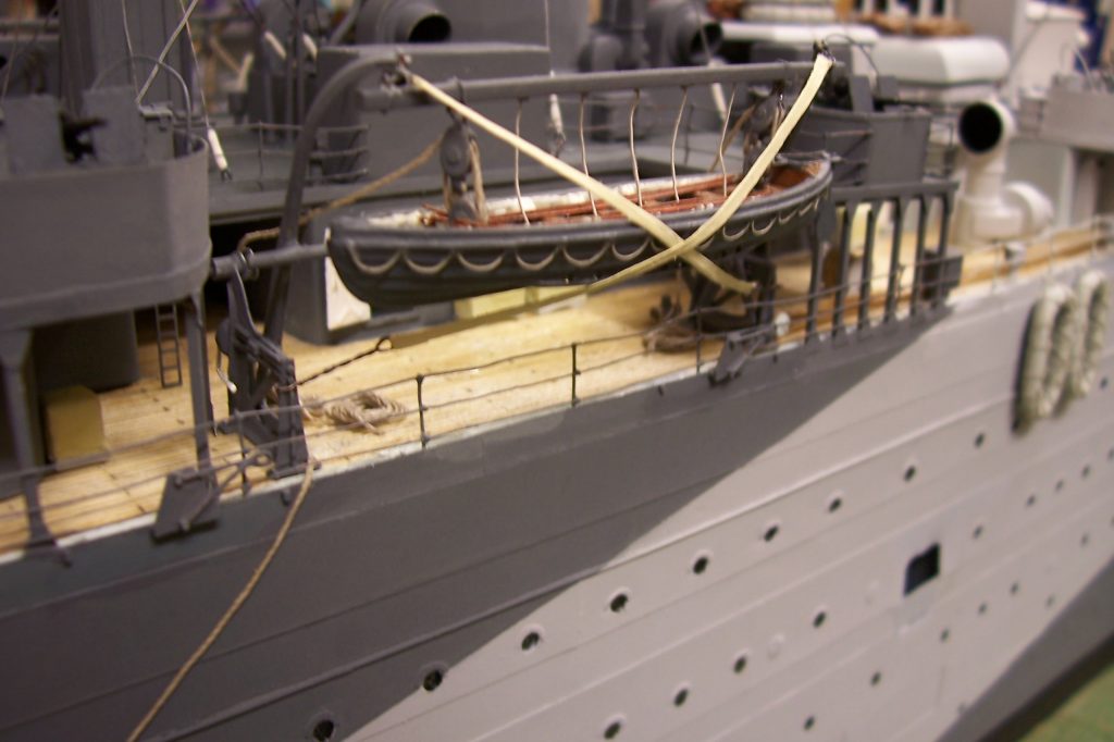
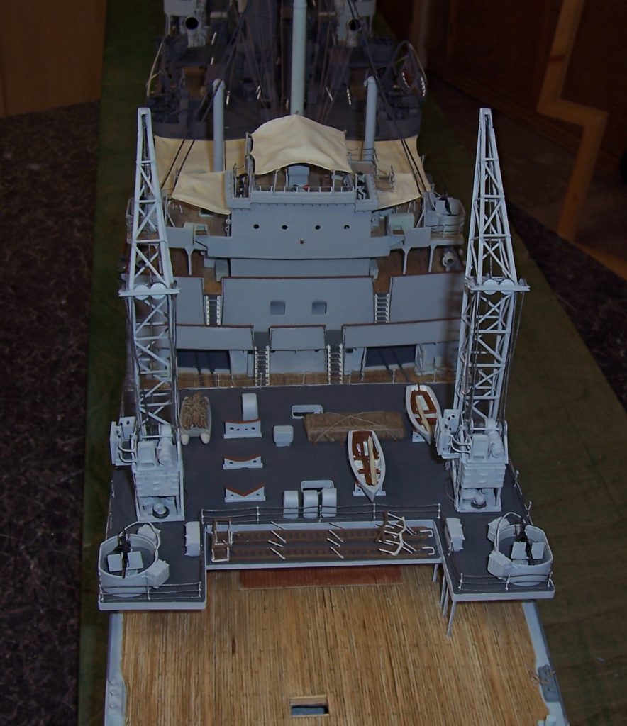
The upper deck is now complete with all the fittings installed along with the davits and rigging for the 27 foot whaler’s.
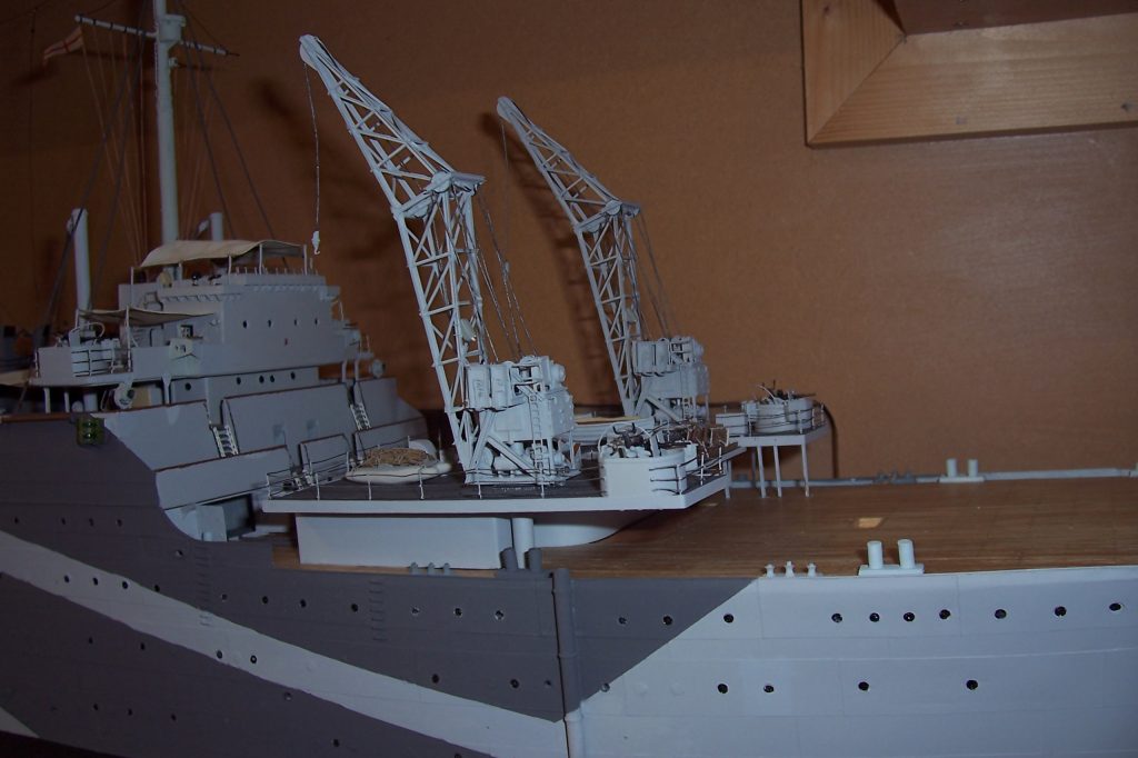
The forward crane superstructure located on the promenade deck is now under construction.
Cranes
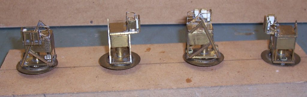
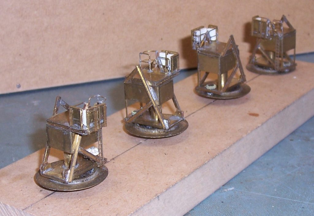
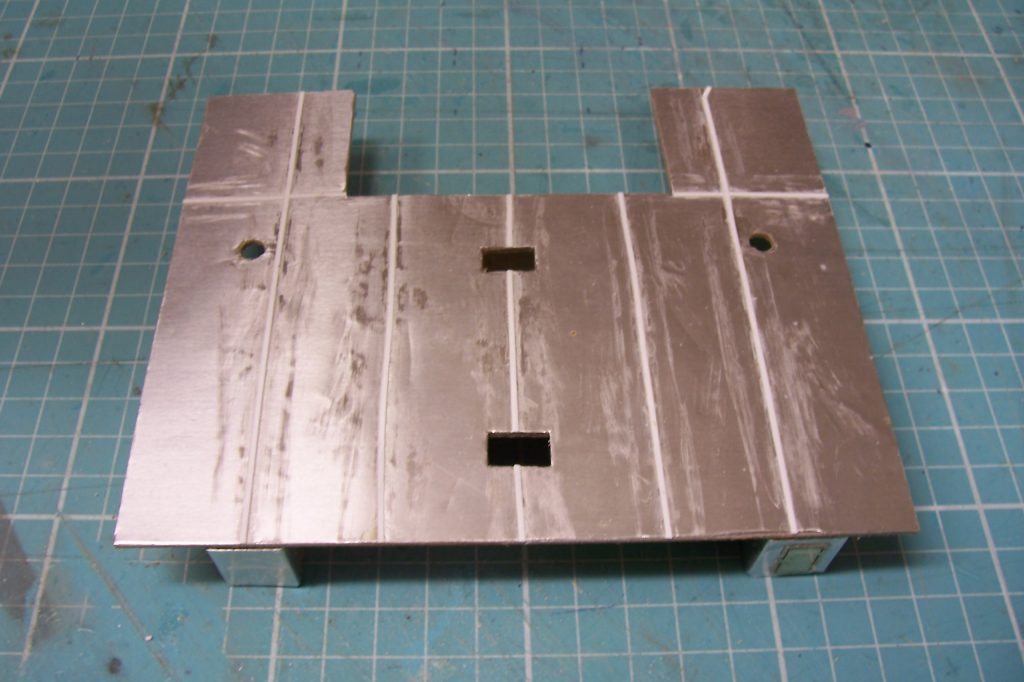
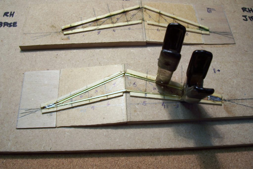
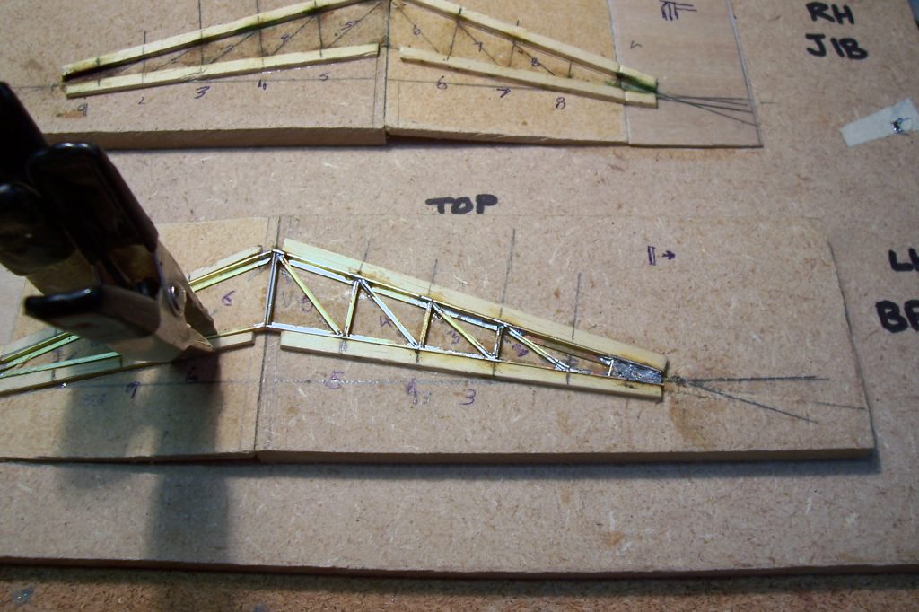
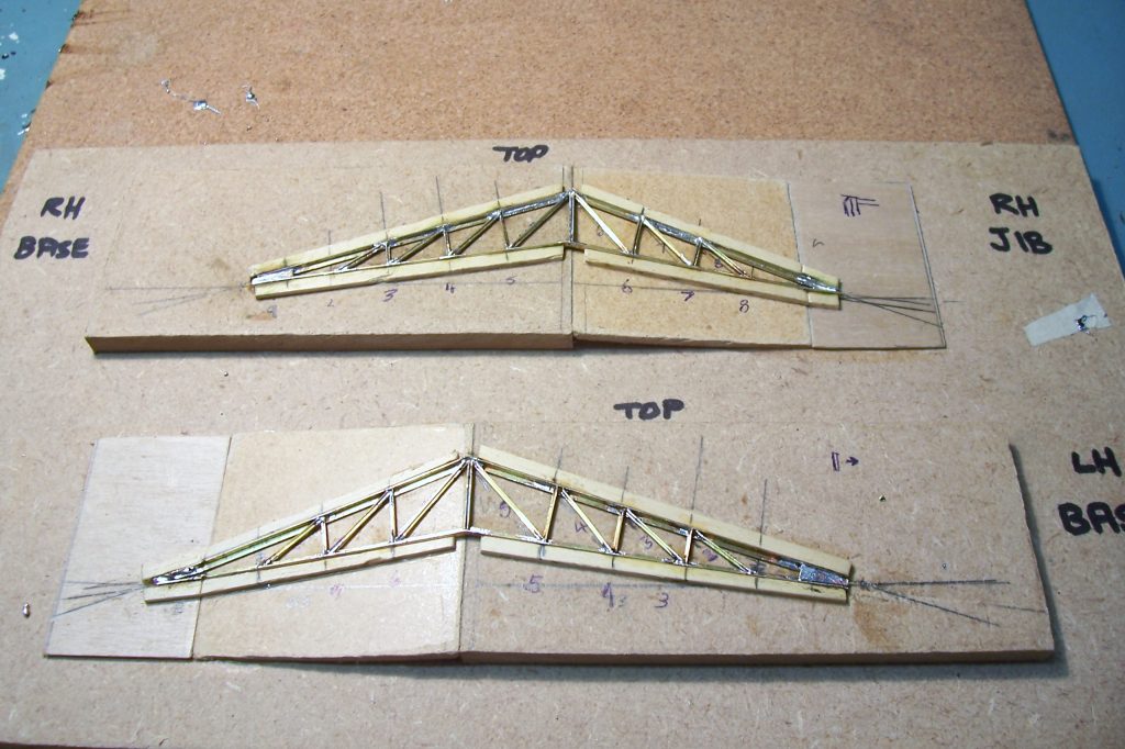
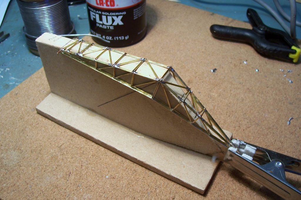
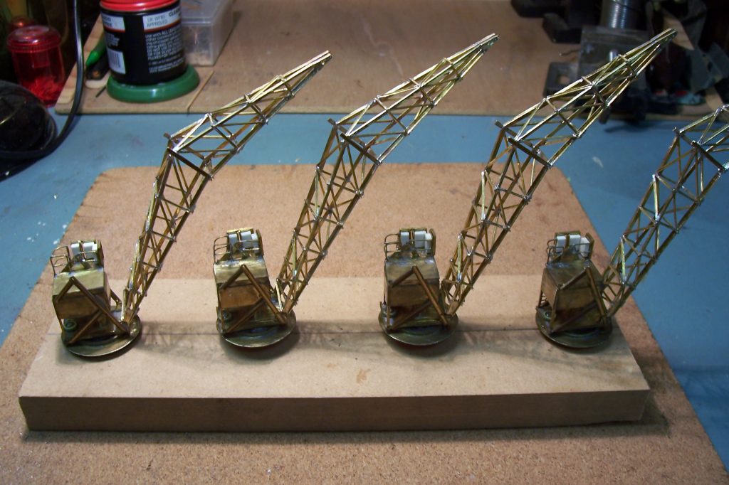
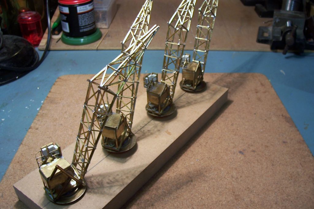
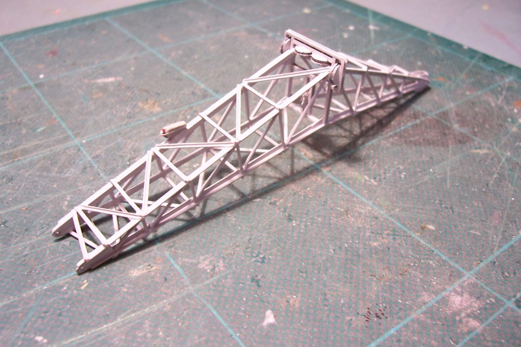
I temporarily suspended work on the upper deck and returned to the cranes. I had started these several years ago and had constructed the bases, but had never finished them as I felt that my soldering skills were not good enough at the time to tackle the crane jibs. I first manufactured jigs to hold the right angle brass sections in place while completing the soldering process. The lattice structure of the jib was then built up, a side at a time, until all four sides were assembled.
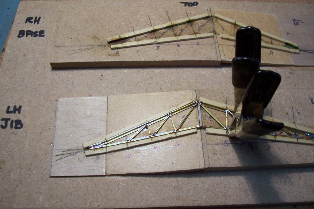
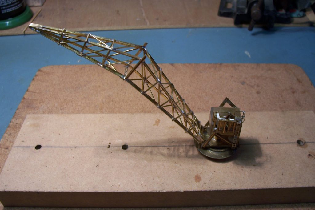
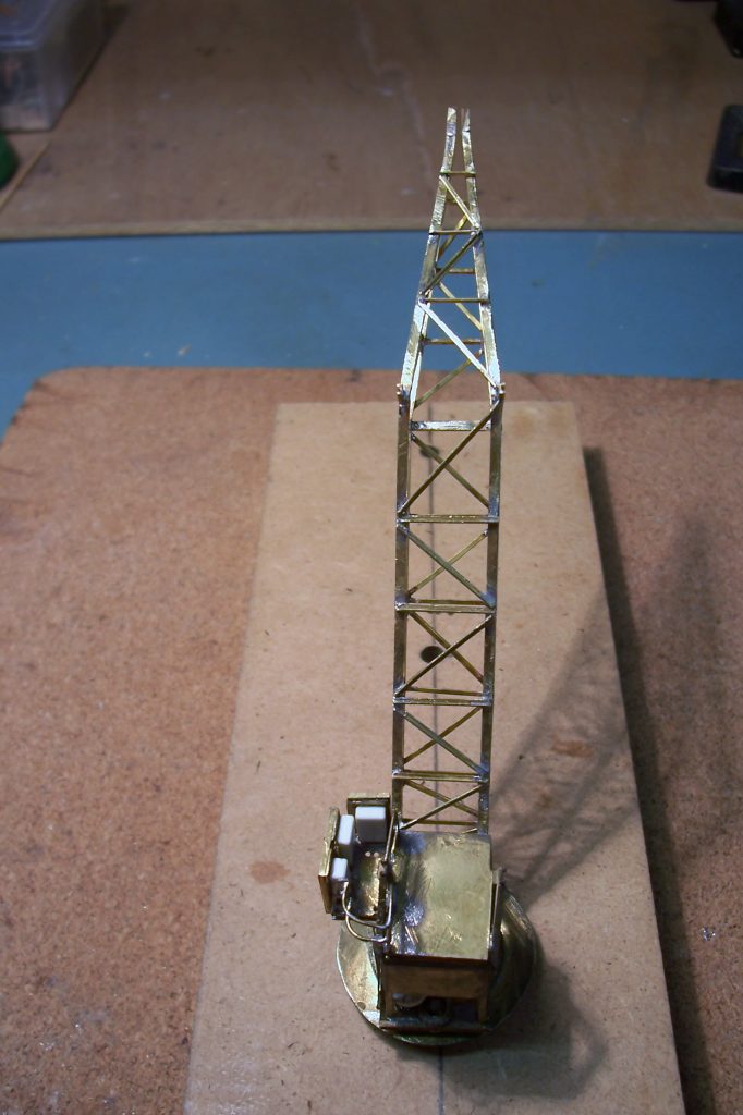
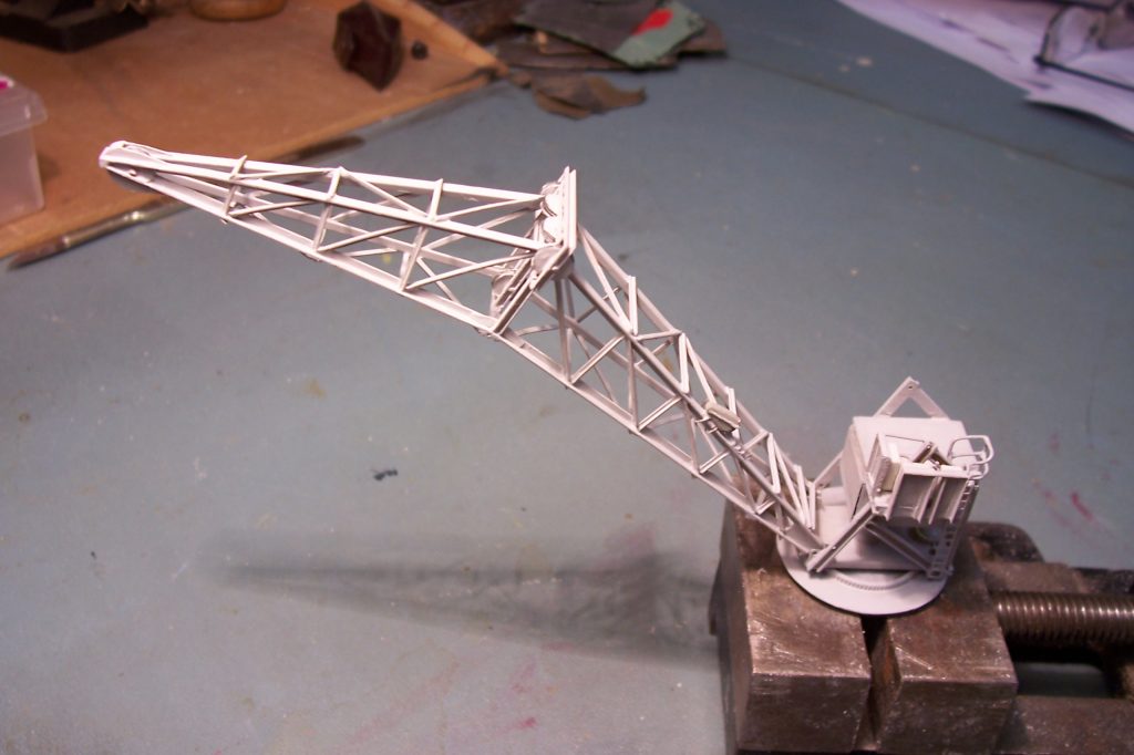
With the soldering completed, the jibs were thoroughly cleaned with soap and water and trial fitted on the crane bases. HMS Ausonia only had three cranes in 1945, but I had made four, using one of these as a trial piece throughout the construction process.
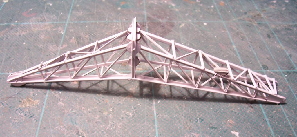
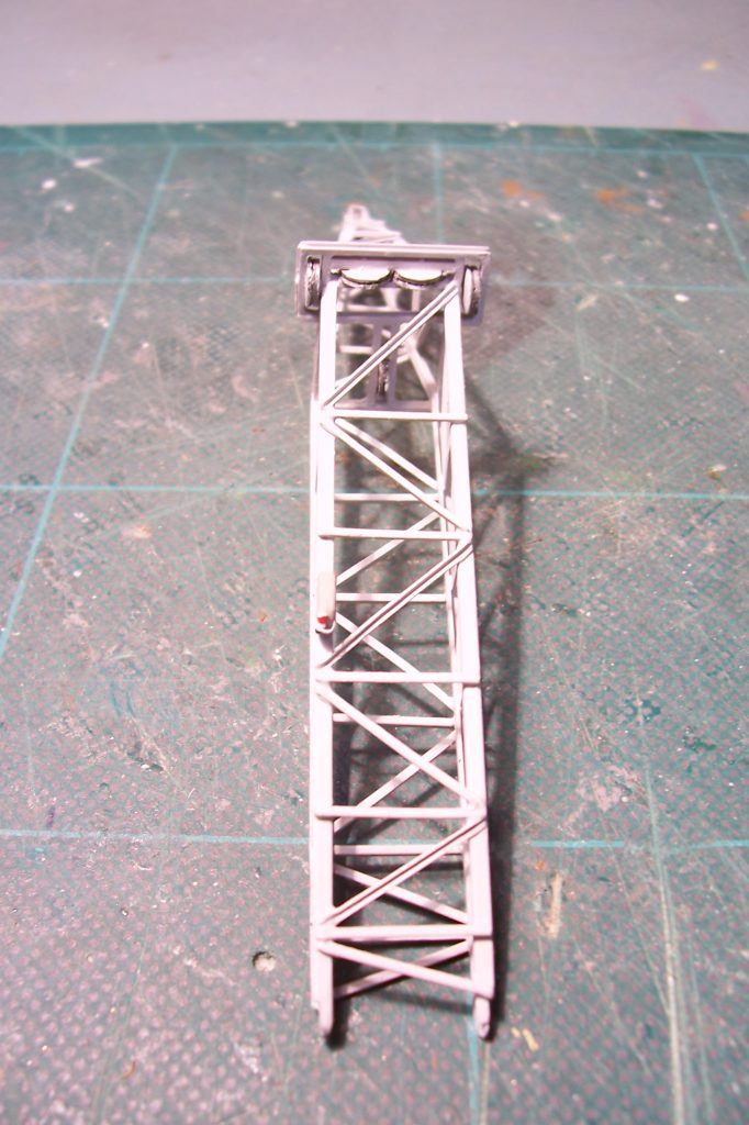
The crane jibs and bases where then sprayed in light grey.
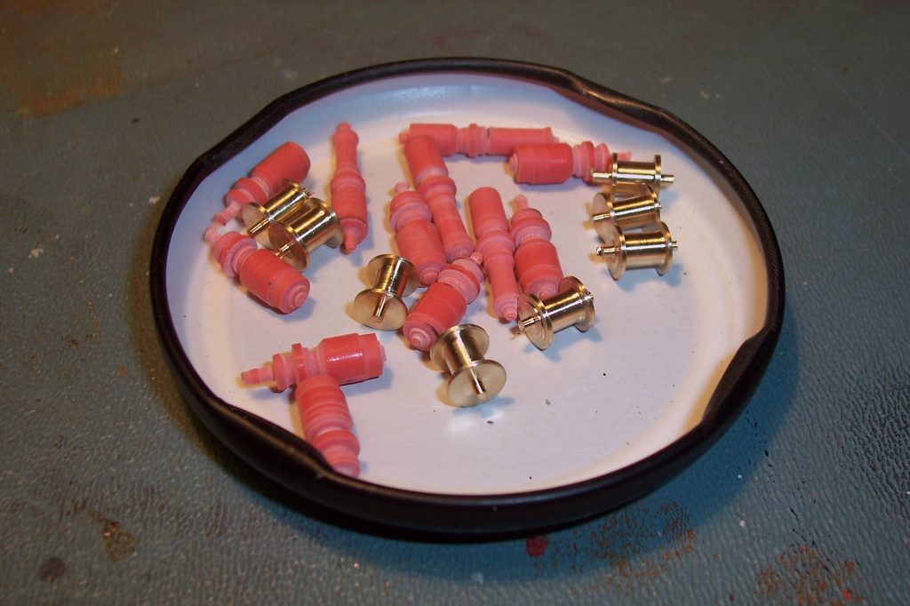
The electric motors and winch drums were turned down on the lathe ready for the assembly to the crane bases.
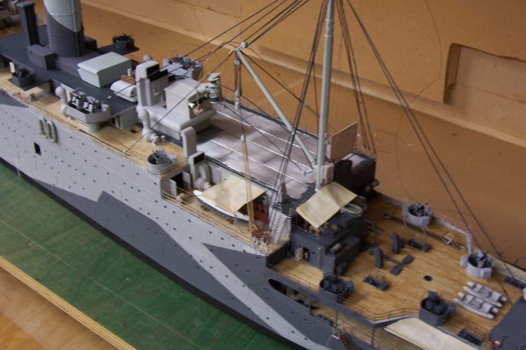
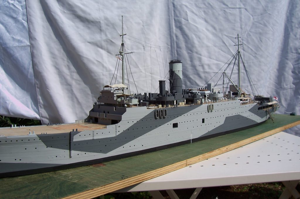
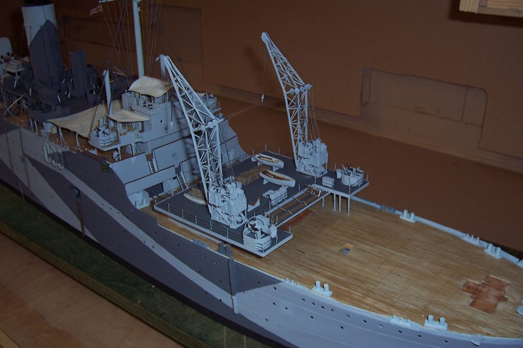
The cranes finally installed on the model.
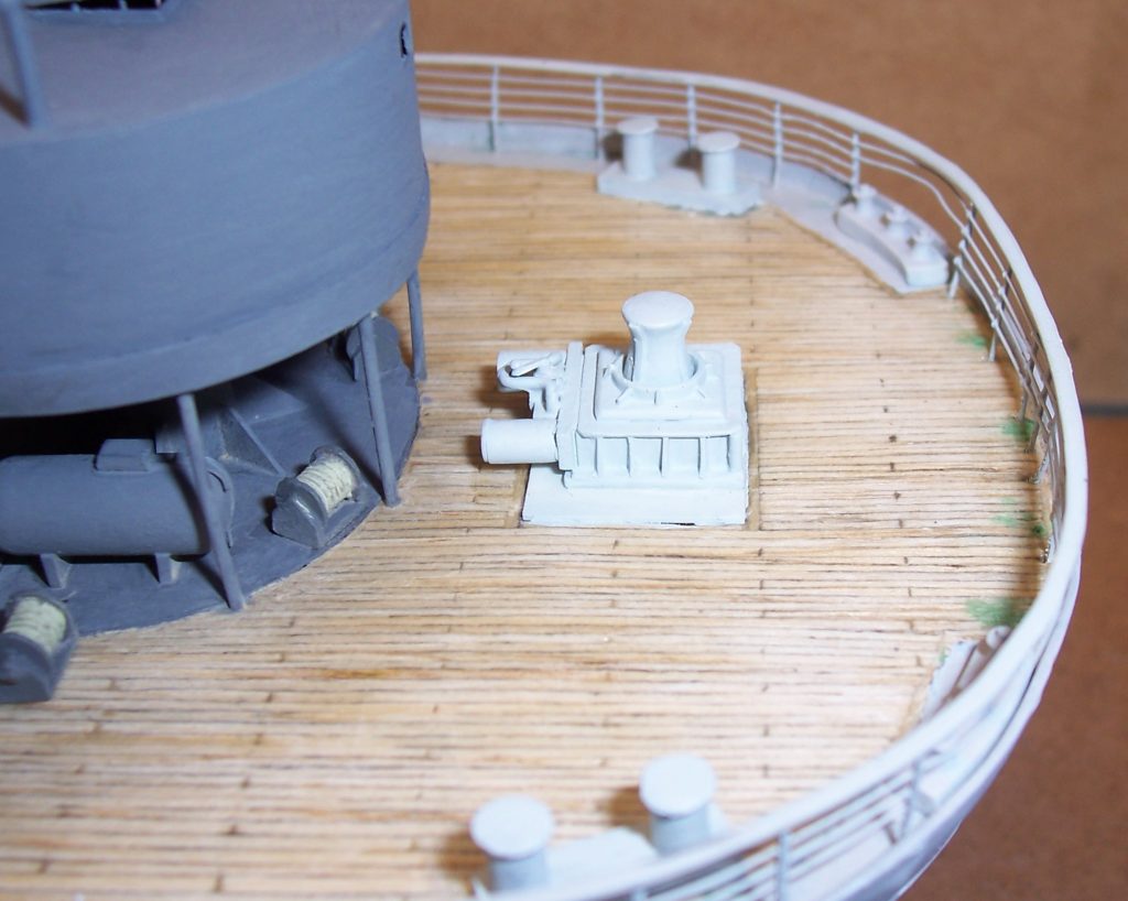
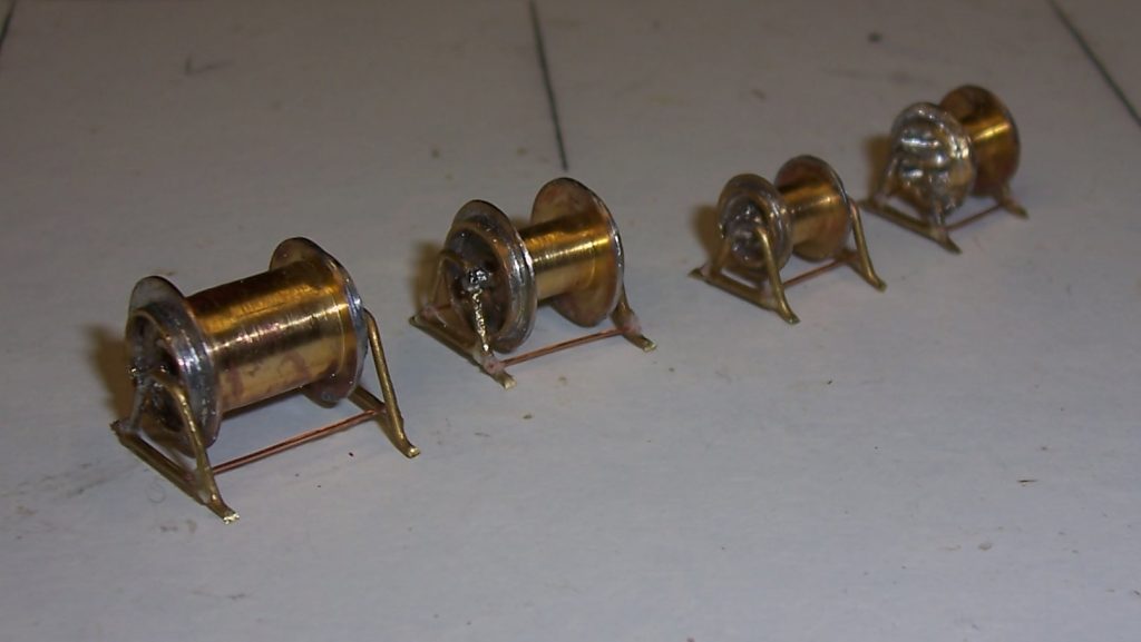
Hawser reels under construction to accompany the forward cranes on the promenade deck.
One day my model will be completed and make it to a display case, but for now it has been returned to my garage, awaiting the time to progress it further.